Suntest
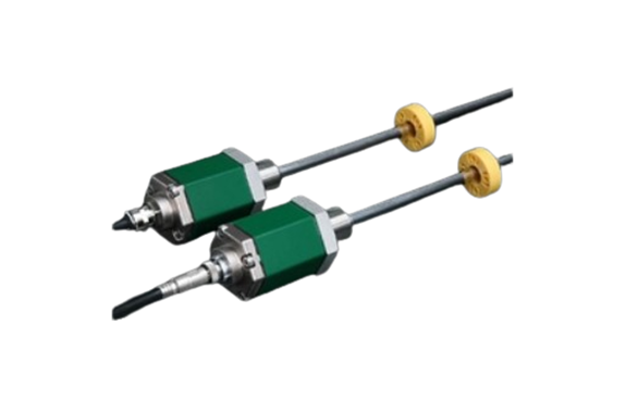
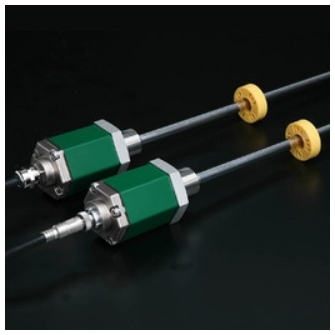
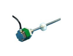
Suntest GY Series GYSE-S Probe
Manufacturer: Suntest Co.,Ltd
Model: GYSE-S
Magnetostrictive Displaiacement Transducer
 Model GY Series are “Displacement Transducers” employing magnetostrictive phenomena, especially the Wiedemann effect. An ultra-sonic wave is generated by a moving magnet operating near a magnetostrictive wave guide on which the sonic wave propagates up to the head of the transducer.
The propagation time is precisely measured by state of the art technology and then the absolute displacement transducer is operational.
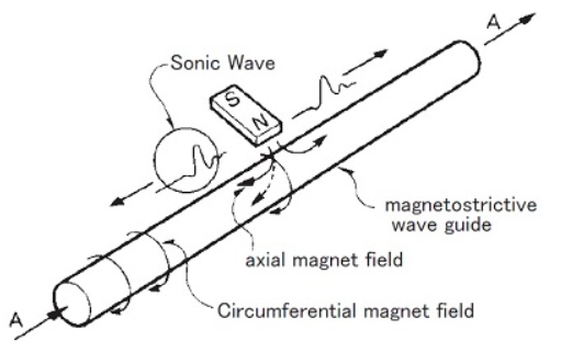
[ Principle ]
The figure shows the fundamental principle of operation.
When a current pulse like A is given to the wave guide, it generates a circumferential magnetic field on the wave guide, then placement of the movable magnet (polarized axially) as shown, only the axial magnetic field of the magnet affecting the wave guide produces a resultant field as indicated by the dotted line.
The vector combination of these two fields produces torsional strain, a phenomenon known as the Wiedemann Effect.
It is a form of vibration and propagates along the wave guide in the form of a transverse ultra-sonic wave.
The GY series displacement transducers detect the propagation time of the ultra-sonic wave.
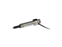
GYSE-S Probe.
SSI output ( detachable probe element )
GYSE-S probe outputs displacement of the magnet as SSI (Synchronous Serial Interface).
SSI is output of a serial communication-type and outputs the position data of 24 〜 27bit.
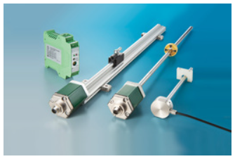
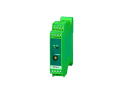
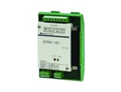
When using SSPC-03 of separate sale, you can convert SSI to parallel data.
So you can get the data in the I/O unit.
The inside probe element can be detached from the outer housing, and with the captive software (GPM), zero and gain adjustment is possible at user side.
- CE marking
- Noise cancellation
- GPM setting
Specifications
| Non-linearity | ≦±0.025%FS ( Typ. ) |
|---|---|
| Resolution | 0.1mm〜0.1μm |
| Repeatablity | ≦±0.001%FS ( Min . ±3μm ) |
| Temp. drift | ≦±15ppmFS/°C |
| Position ( Std. ) | SSI ( Synchronized Serial Interface ), 24〜27bit, Binary(Std.) or Gray |
| Velocity ( option ) | not available |
| Alarm | Open drain 50V 0.1A ( for lost magnet ) |
| Power supply | +24(±2)VDC (70mA) |
| Sampling freq.(*) | Std. 1kHz ( Total rod length : 1300mm ) |
| Max. Pressure | 35MPa ( probe rod ) |
| Operating temp. | -20°C〜+75°C |
| Storage temp. | -40°C〜+75°C |
| Vibration | 15G ( 20〜100Hz ) |
| Shock | 100G ( 2msec ) |
| IP grade | IP67 |
- The above mentioned accuracy applies to sensors with an effective stroke of 300mm or more.
- The specification of stroke less than 300mm is equal that of stroke 300mm.
(*) Sampling freq. is available to Max. 3.75kHz by option. It depends on the
total rod length (shows in Model ⑬), and the consumption current increases.
Model No.
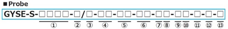
① Effective stroke
15〜7500mm
② Head dead zone
50 :50mm (Std.)
□ :□mm ( option ) ( specified by customers )
・Possible Min. length depends on the selected magnet or float.
③ Tip dead zone
□:70mm/ 90mm/ 100mm(Std.)
・S (Std. length) depends on the selected magnet or float in ⑤.
| □ | tip DZ | magnet | float |
|---|---|---|---|
| 70 | 70mm | M2PN, M0SM, M0LM, M3, M11N, BA | F25N, F28N |
| 90 | 90mm | F28S, F30S | |
| 100 | 100mm | T144, T163 | F40S, F42S, F50S, F54S |
□ :□mm ( option ) ( specified by customers )
・Possible Min. length depends on the selected magnet or float.
④ Thread / Rod diameter
M :M24xP1.0, rod Φ10(Std.)
N :M18xP1.5, rod Φ10
U :3/4-16UNF-3A, rod Φ10
M8 :M24xP1.0, rod Φ8
N8 :M18xP1.5, rod Φ8
U8 :3/4-16UNF-3A, rod Φ8
M14 :M24xP1.0, rod Φ13.8
Z :Probe inside element only (without outer housing)
⑤ Associated magnet or float
| magnet | float |
|---|---|
| M2PN :No.2PN (Std.) M0SM :No.ΦSPM M0LM :No.ΦLPM M3 :No.3 M11N :No.11N T144 :No.T14-M4 T163 :No.T16-M3 BA : No.2KYN-17-LG | F28S :Φ28 SS316L F30S :Φ30 SS316L F40S :Φ40 SS316(B) F42S :Φ43 SS316L F50S :Φ50 SS316L F54S :Φ54 SS304 F25N :RF-A10 plastic F28N :RF-A6 plastic |
・Selecting magnet from page 116〜118(GG).
・Please consult our factory in case of requesting special magnet or float.
・This model code means only specifying associated magnet or float.
・Ordering magnet or float individually.
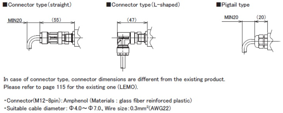
⑥ Cable connection
8P:Connector (M12-8pin)
△G□F:pigtail / cable end : free
△G□A:pigtail / cable end : with connector for relay
(□:cable length(m)、Max.10m)(*)
(△:cable type
S:standard, H:high temp. cable, R:robot cable, UL:cUL cable)
CN:existing connector (Please refer to page 115 of option.)
(*) In case of cable 10m or more, please use extension cable.
・Please confirm extension cable on page 120-122.
・Ordering loose mating connector individually.
⑦ Resolution
D2:0.1mm
D3:0.05mm
D4:0.01mm (Std.)
D5:0.005mm
D7:0.002mm
D8:0.001mm
DF:0.5μm
DG:0.2μm
DH:0.1μm
⑧ Linearity option
blank:without option
L : Linearization option (at room temperature).
⑨ Direction
D:When magnet moves toward tip, output increase
R:When magnet moves toward tip, output decrease
⑩ Number of bits
4:24bit (Std.)
5:25bit
6:26bit
7:27bit
⑪ Output code
B:Binary(Std.)
G:Gray
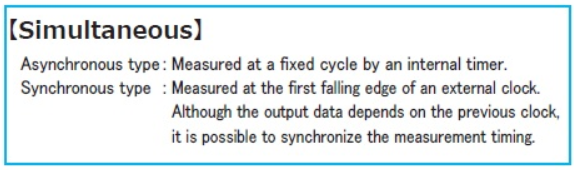
⑫ Synchronous
5A:asynchronous SSI
5S:synchronous SSI
⑬ Option
blank:without option
SRT:SRT option (Recommendation:pigtail type)
・Please confirm the details of SRT option on page 114.
High-frequency sampling:
Only when “5A (asynchronous)” is selected in ⑫.
X2:2kHz sampling (total rod length : Max.700mm)
X3:3kHz sampling (total rod length : Max.500mm)
X4:3.75kHz sampling (total rod length : Max.400mm)
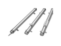
Dimensions
Probe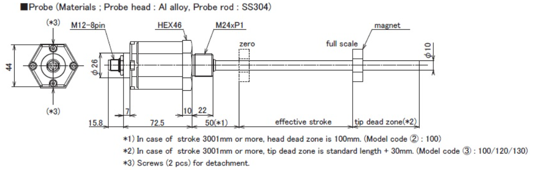
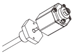
Detachable probe element
Connecter & Pigtail
Cable
| Wire color | Pin number | Function |
|---|---|---|
| red | 1 | +24VDC |
| white | 2 | 0V |
| blue | 3 | DATA+ |
| green | 4 | DATA- |
| brown | 5 | CLK+ |
| black | 6 | CLK- |
| yellow | 7 | Alarm |
Shield should be connected to FG of user’s unit.
REQUEST QUOTATION

PAYMENT

LINK


