Suntest
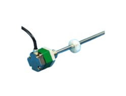
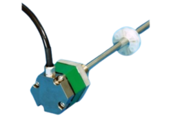
Suntest GYRHP-MR6 Probe
Manufacturer: Suntest Co.,Ltd
Model: GYRHP-MR6
Magnetostrictive Displaiacement Transducer
 Model GY Series are “Displacement Transducers” employing magnetostrictive phenomena, especially the Wiedemann effect. An ultra-sonic wave is generated by a moving magnet operating near a magnetostrictive wave guide on which the sonic wave propagates up to the head of the transducer.
The propagation time is precisely measured by state of the art technology and then the absolute displacement transducer is operational.
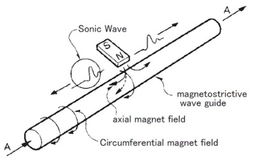
[ Principle ]
The figure shows the fundamental principle of operation.
When a current pulse like A is given to the wave guide, it generates a circumferential magnetic field on the wave guide, then placement of the movable magnet (polarized axially) as shown, only the axial magnetic field of the magnet affecting the wave guide produces a resultant field as indicated by the dotted line.
The vector combination of these two fields produces torsional strain, a phenomenon known as the Wiedemann Effect.
It is a form of vibration and propagates along the wave guide in the form of a transverse ultra-sonic wave.
The GY series displacement transducers detect the propagation time of the ultra-sonic wave.
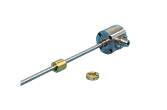
GYRHP-MR6 Probe
Pressure resistance rod : 70MPa, heavy duty type
(with external controller)
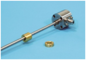
GYRHP-MR6, which is different from conventional GY series, achieved pressure-resistant 70MPa (rod) by redesign in head and rod part. Standard of protection grade is IP67, but you can select water-proof type (IP68) or cable conduit type (IP69K) by option. Between probe and controller, RS-422 differential line driver transmission, providing robustness against electrical noise, is used. In combination with a digital output controller, Min. 1μm resolution is possible. And by auto calibration function, difference in the output when you exchange the probe is adjusted automatically.
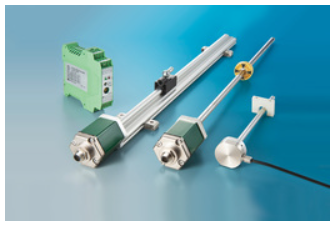
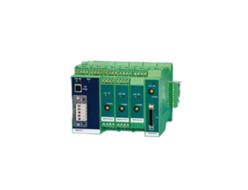
◆Associated controller
- Analogue output : GYHC
- Digita output : GYDC-S1, GYDC-05
- IRDS-GY: When using the IRDM, you can connect with CC-Link, CC-Link IE Field, PROFIBUS, EtherNet/IP, and EtherCAT.
- DC-Q: MELSEC-Q built-in unit
Specifications
| Non-linearity | ≦±0.025%FS (Typ.) |
|---|---|
| Resolution | (Analogue) 16bit (Digital) Min. 1μm |
| Repeatability | ≦±0.001%FS |
| Temp. drift | ≦±20ppmFS / °C |
| Max. Pressure | 70MPa ( probe rod ) |
| Operating temp. | -20°C〜+80°C |
| Storage temp. | -40°C〜+80°C |
| Vibration | 15G ( 10〜2000Hz ) |
| Shock | 100G ( 2msec ) / 800G ( SRT option ) |
| IP grade | IP67(Std.), IP68 / IP69K (option) |
- The specification of stroke less than 300mm is equal that of stroke 300mm.
- The above mentioned accuracy applies to sensors with an effective stroke of 300mm or more.
Model No.
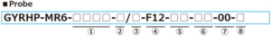
① Effective stroke
15〜1000mm
② Head dead zone
50 :50mm(Std.)
□ :□mm(specified by customers)
- Possible Min. length depends on the selected ma
③Tip dead zone
70 : 70mm(in case ⑤ is BA)
100 : 100mm(in case ⑤ is T163)
□ : □mm (specified by customers)
④ Mount / Rod diameter
F12 :pressure-resistant flange, rod Φ12 (Std.)
⑤ Associated magnet
BA :No.2KYN-17-LG (Std.)
T163 :No.T16-M3
- Please consult our factory in case of requesting special magnet.
- This model code means only specifying associated magnet.
- Ordering magnet individually.
⑥ Cable connection
○△G□◇F : pigtail / cable end : free (Std.)
○△G□◇A : pigtail / cable end : with connector for relay
WP3G□◇F : pigtail of water proof cable / cable end : free
WP3G□◇A : pigtail pf water proof cable / cable end : with connector for relay
○ : pigtail type (S : standard, C : cable conduit)
△ : cable type (S : standard, H : high temp. cable, R : robot cable, UL : cUL cable)
□ : cable length (m) Max.10m(*)
◇ : head shape type (L : radial, S : axial)
(*)In case of using extension cable, sensor cable (m) + extension cable (m) ≦ 200m.
⑦ Position output
00 : depends on external controller
⑧ Option
blank : without option
SRT : SRT option
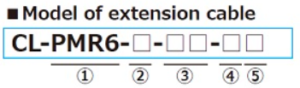
① Probe
PMR6:GYRHP-MR6
② Cable type
S : Standard cable
H : High temp. cable
R : Robot cable
W : Water proof cable
UL : cUL cable
③ Cable length (m)
④ Cable end (sensor side)
F : free
S : with straight connector
⑤ Cable end (controller side)
F : free
A : with connector for relay
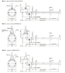
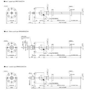
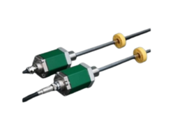
Dimensions
Dimensions (Radial)
Dimensions (Axizl)
Cable
| Function | cable end : free Wire color | cable end : with connector Pin number |
|---|---|---|
| sensor power | red | 1 |
| N.C. | yellow | 2 |
| 0V | white | 3 |
| shield / drain wire | ||
| START(+) | green | 4 |
| STOP(+) | black | 5 |
| START(−) | blue | 6 |
| STOP(−) | brown | 7 |

REQUEST QUOTATION

PAYMENT

LINK


