Hakaru
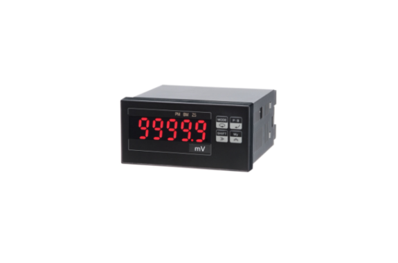
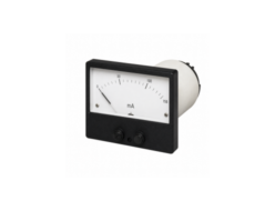
Hakaru DPXC Digital Panel Meter, DC Ammeter, Voltmeter
Manufacturer: HAKARU PLUS CORPORATION
Model: DPXC
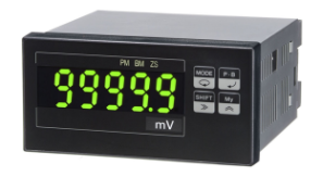
96 × 48, 5 digits, digit height 15 mm
Model
DPXC-(1)-(2)(3)-(4)-(5)
(1) Measurement Range
| Type | Code | Measurement Range |
|---|---|---|
| Voltmeter | 01 | ±19.999mV |
| V1 | ±100.00mV | |
| 02 | ±199.99mV | |
| 04 | ±1.9999V | |
| 04 | ±19.999V | |
| 04 | ±399.9V | |
| 06 | ±699.9V | |
| Ammeter | 11 | ±19.999µA |
| 12 | ±199.99µA | |
| 14 | ±1.9999mA | |
| 14 | ±19.999mA | |
| 14 | ±199.99mA | |
| Receiver Meter | 49 | DC1 to 5V |
| 49 | DC0 to 5V | |
| 49 | DC4 to 20mA | |
| 49R | DC4 to 20mA |
(2) Power Supply
| Code | Description |
|---|---|
| A | AC100 to 240V |
| B | DC12 to 24V |
| C | DC110V |
(3) Sensor Power Supply
| Code | Description |
|---|---|
| No code | None |
| 2 | DC5V ±10% |
| 3 | DC12V ±5% |
| 5 | DC24V ±5% |
(4) Data Output 1
| Code | Description |
|---|---|
| No code | None |
| 09 | DC1 to 5V |
| 29 | DC4 to 20mA |
| BP | BCD output, TTL level, positive logic |
| BN | BCD output, TTL level, negative logic |
| DP | BCD output, transistor output, source type |
| DN | BCD output, transistor output, sink type |
| E0 | RS-232C |
| E1 | RS-485 |
| EC | Decimal-point external control |
(5) Data Output 2
| Code | Description |
|---|---|
| No code | None |
| E0 | RS-232C |
| E1 | RS-485 |
| EC | Decimal-point external control |
Note: Data Output 2 can be added when Data Output 1 is 09 or 29.
How to Order Example
Model: DPXC-01-A3-09-E0
Special Specification:
Device Specifications
Display Section
Numeric range: 0 to 99999
Display element: Red LED or green LED, digit height 15.2mm. Display color can be freely selected.
Polarity input: “−” display
Decimal point position: Lights at any decimal point position.
Input overrange: When 99999 is exceeded, 00000 flashes. For the 699.9V rated product, the full-scale value flashes when 699 is exceeded.
Scaling Function
Full-scale display: -99999 to +99999
Offset display: -9999 to +99999
Resolution: 1/10000
Hold
Holds the display value, data output, current value, peak memory value, bottom memory value, maximum value, and comparison output. Active “L”.
Alarm Reset
Without isolation from input. Restores the comparison output. Active “L”.
Zero Set
Without isolation from input. Electrically sets the initial input value to zero.
Offset Fixed Display
When the input is below the offset value, the display is fixed to the offset display value.
10⁰ Digit Fixed Display
The display value of the 10⁰ digit is fixed to 0.
Sampling period: 15 times/second
Display period: Selectable from 67ms, 400ms, 1s, 2s, 4s, or 5s.
Average Calculation
The display value is averaged by interval average or moving average within the display period.
| Display Period | Number of Measurement Data for Averaging |
|---|---|
| 67ms | No averaging |
| 400ms | 6 |
| 1s | 15 |
| 2s | 30 |
| 4s | 60 |
| 5s | 75 |
For moving average, the display period is fixed at 67ms.
The number of moving-average measurement data can be selected from 2, 4, 8, 16, or 32.
Response: The longer one between within 2 sampling cycles or 1 display period.
Input type: Single-ended floating input
A/D conversion section: Sigma-delta conversion method
Unit seal: Included
Input Specifications
Input resistance and overload:
| Type | Measurement Range | Input Resistance | Input Overload | Terminal No. |
|---|---|---|---|---|
| Voltmeter | 01 : ±19.999mV | 5MΩ | DC±50V | ①-④ |
| V1 : ±100.00mV | 5MΩ | DC±50V | ①-④ | |
| 02 : ±199.99mV | 120kΩ | DC±50V | ①-④ | |
| 04 : ±1.9999V | 1MΩ | DC±250V | ①-④ | |
| 04 : ±19.999V | 10MΩ | DC±250V | ②-④ | |
| 04 : ±399.9V | 10MΩ | DC±750V | ③-④ | |
| 06 : ±699.9V | 10MΩ | DC±750V | ③-④ | |
| Ammeter | 11 : ±19.999µA | 10kΩ | DC±2mA | ①-④ |
| 12 : ±199.99µA | 1kΩ | DC±20mA | ①-④ | |
| 14 : ±1.9999mA | 100Ω | DC±50mA | ①-④ | |
| 14 : ±19.999mA | 11Ω | DC±150mA | ②-④ | |
| 14 : ±199.99mA | 1Ω | DC±500mA | ③-④ | |
| Receiver Meter | 49 : DC1 to 5V | 1MΩ | DC±250V | ①-④ |
| 49 : DC0 to 5V | 1MΩ | DC±250V | ②-④ | |
| 49 : DC4 to 20mA | 12.4Ω | DC±150mA | ③-④ | |
| 49R : DC4 to 20mA | 250Ω | DC±40mA | ①-④ |
Analog Output Specifications
Allowable error: ±0.15%
Temperature coefficient: 200ppm/°C
Resolution: 1/10000
Output period: 67ms
Output response: Within 300ms for input
| Output Range | Output Impedance | Allowable Load Resistance |
|---|---|---|
| DC1 to 5V | 0.1Ω or less | 500Ω or more |
| DC4 to 20mA | 5MΩ or more | 0 to 600Ω |
BCD Output Specifications
TTL Level Output
Data output: Parallel BCD code, 1-2-4-8, latch output
TTL level: C-MOS compatible, Fo = 2
Control output:
Overrange (OVER): Logic “1” during overrange
Polarity (POL): Logic “1” during positive polarity
Synchronous signal (SYNC): 10ms “L” pulse
Control input:
Latch: Active “L”
Memory function: Active “L”
Data inhibit: Active “H”
Transistor Output
Output capacity: DC30V, 30mA max.
Data output: Parallel BCD code, 1-2-4-8, latch output
“1” output: Transistor ON
Control output:
Overrange (OVER): ON during overrange
Polarity (POL): ON during positive polarity
Synchronous signal (SYNC): 10ms ON
Control input:
Latch: Active ON
Memory function: Active ON
Data inhibit: Active OFF
Serial Communication
RS-232C, RS-485
Transmission method: Asynchronous half-duplex method
Communication speed: 4800, 9600, 19200, 38400bps
Transmission code: Conforms to JIS 8-unit code
Data format:
Data bit length: 7 bits or 8 bits
Stop bit length: 2 bits or 1 bit
Parity check: Even, odd, or none
Error detection: Vertical parity and BCC
Installation Specifications
Power supply: AC100 to 240V, 50/60Hz, DC12 to 24V, DC110V
Power supply allowable range: AC90 to 250V, DC9 to 32V, DC100 to 170V
Power consumption:
| Power Supply | Power Consumption |
|---|---|
| AC100V | Approx. 7VA |
| AC200V | Approx. 9VA |
| DC12V | Approx. 300mA |
| DC24V | Approx. 150mA |
| DC110V | Approx. 30mA |
Operating temperature range: 0 to 50°C
Storage temperature: -20 to 70°C
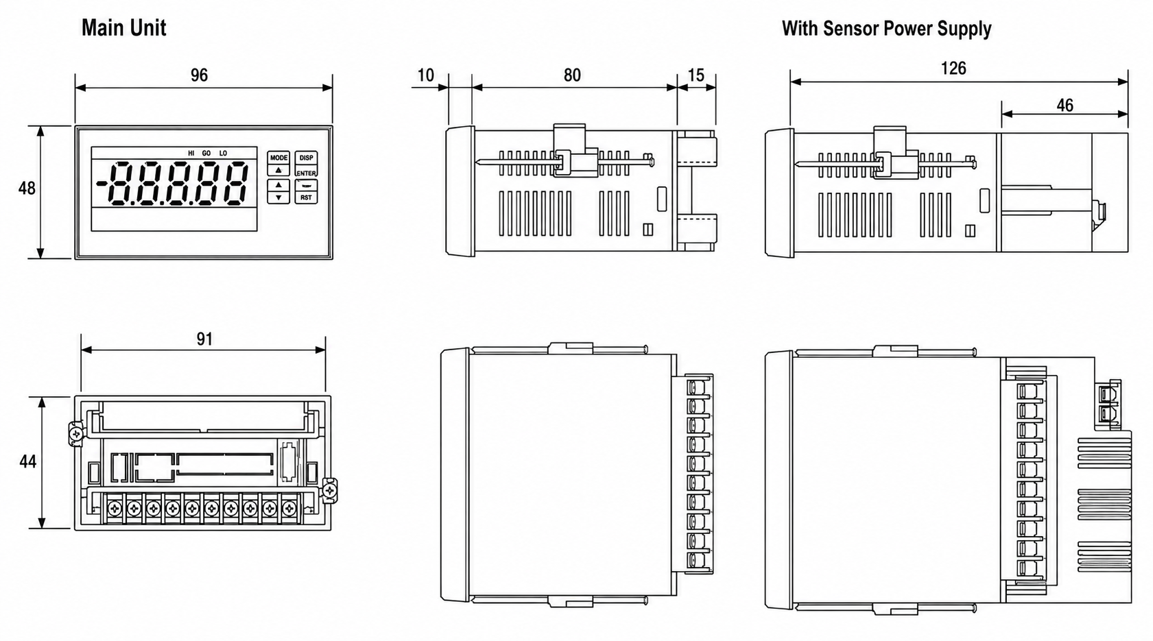
Dimensions: W96 × H48 × D90
Mass: Approx. 300g
Protective structure: Front panel section equivalent to IP65
Performance
Temperature coefficient: ±200ppm/°C
Noise rejection ratio:
Normal mode: 50dB or more
Common mode: 110dB or more
Power line mixed noise: 1000V
Insulation resistance: DC500V, 100MΩ or more
Dielectric strength:
Between input and external case: AC2000V for 1 minute
Between power supply and external case: AC2000V for 1 minute
Between power supply and input/output: AC1500V for 1 minute
Between input/output and power supply: AC500V for 1 minute
| Type | Measurement Range | Accuracy |
|---|---|---|
| Voltmeter | 01 : ±19.999mV | ±(0.05% + 5digit) |
| V1 : ±100.00mV | ±(0.05% + 5digit) | |
| 02 : ±199.99mV | ±(0.05% + 3digit) | |
| 04 : ±1.9999V | ±(0.1% + 1digit) | |
| 04 : ±19.999V | ±(0.1% + 1digit) | |
| 04 : ±399.9V | ±(0.1% + 3digit) | |
| 06 : ±699.9V | ±(0.1% + 3digit) | |
| Ammeter | 11 : ±19.99µA | ±(0.05% + 3digit) |
| 12 : ±199.9µA | ±(0.05% + 3digit) | |
| 14 : ±1.999mA | ±(0.1% + 1digit) | |
| 14 : ±19.99mA | ±(0.1% + 1digit) | |
| 14 : ±199.9mA | ±(0.1% + 1digit) | |
| Receiver Meter | 49 : 1 to 5V | ±(0.1% + 1digit) |
| 49 : 0 to 5V | ±(0.1% + 1digit) | |
| 49 : 4 to 20mA | ±(0.1% + 1digit) | |
| 49R : 4 to 20mA | ±(0.1% + 3digit) |
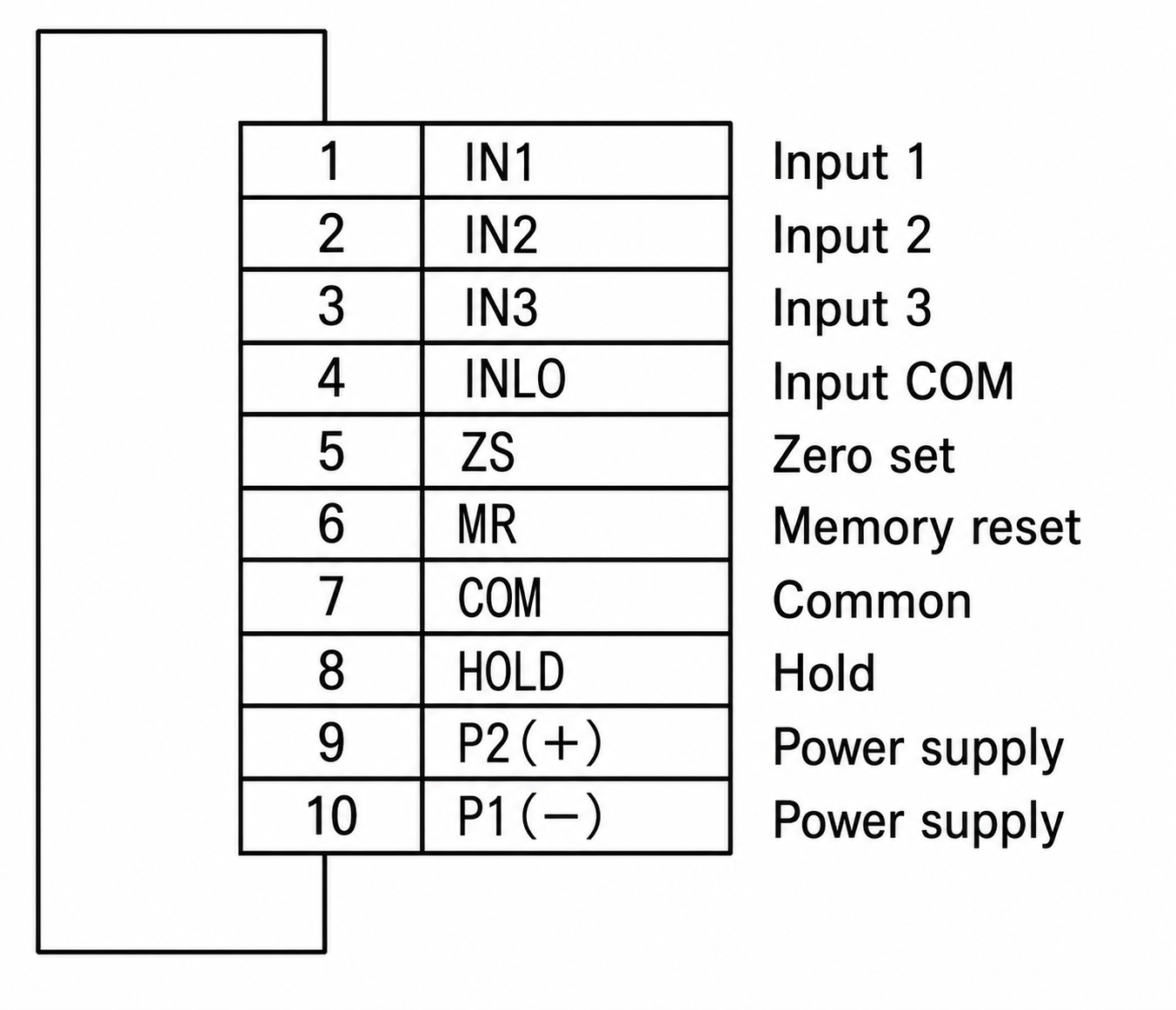
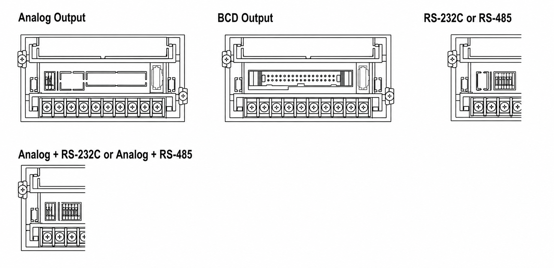
Connection Diagram
Lower terminals
Option, Middle Section
Sensor Power Supply
Sensor power supply unit rear side, screwless terminal
| C11 | C12 |
|---|---|
| +V | 0V |
Analog Output
Screwless terminal
| C1 | C2 |
|---|---|
| + OUT | − OUT |
BCD Output
| Use | Bit | Pin No. | Pin No. | Bit | Use |
|---|---|---|---|---|---|
| 10¹ | 1 | 1 | 2 | 1 | 10⁰ |
| 2 | 3 | 4 | 2 | ||
| 4 | 5 | 6 | 4 | ||
| 8 | 7 | 8 | 8 | ||
| 10³ | 1 | 9 | 10 | 1 | 10² |
| 2 | 11 | 12 | 2 | ||
| 4 | 13 | 14 | 4 | ||
| 8 | 15 | 16 | 8 | ||
| NC | 17 | 18 | 1 | 10⁴ | |
| 19 | 20 | 2 | |||
| 21 | 22 | 4 | |||
| 23 | 24 | 8 | |||
| POL | 25 | 26 | MEMORY RESET | ||
| OVER | 27 | 28 | OUTPUT ENABLE | ||
| SYNC | 29 | 30 | LATCH | ||
| BOTTOM MEMORY | 31 | 32 | PEAK MEMORY | ||
| DATA COM | 33 | 34 | DATA COM | ||
RS-232C or RS-485
Screwless terminal
| C3 | C4 | C5 | C6 | C7 | |
|---|---|---|---|---|---|
| RS-232C | SD | RS | RD | CS | SG |
| RS-485 | Terminator | NC | + | − | |
Analog Output + RS-232C or RS-485
Screwless terminal
| C1 | C2 | C3 | C4 | C5 | C6 | C7 | |
|---|---|---|---|---|---|---|---|
| RS-232C | + OUT | − OUT | SD | RS | RD | CS | SG |
| RS-485 | + OUT | − OUT | Terminator | NC | + | − | |
Outline Drawing (Unit: mm)
Terminal Arrangement Diagram
Mounting Dimensions Drawing (Unit: mm)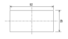
Related Products
-
Hakaru FDW-121 And FDW-141 3-Color Bar Graph Meter (Digital Display And Alarm)
-
Hakaru TRP-M1LM Thin Limiter Converter
-
Hakaru RRQK-F Rectangular (83 x 100) AC Voltmeter (Rectifier Type)
-
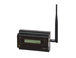
Hakaru HLR-A8-OUT LoRa Radio Analog 8-Point Output Model
-

Hakaru RRF-G Rectangular (83 x 83) Frequency Meter (Transducer Type)
-
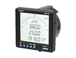
Hakaru XS2-110 Electronic Multimeter Standard
REQUEST QUOTATION

PAYMENT

LINK


