- Home
- Products
- Hakaru DMH Digital Meter Relay: DC Ammeter, DC Voltmeter, Receiving Meter, AC Ammeter, AC Voltmeter
Hakaru
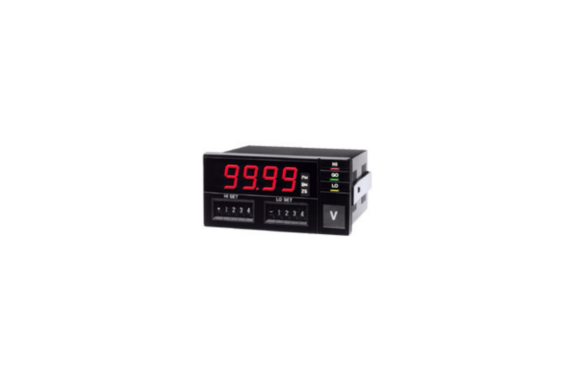
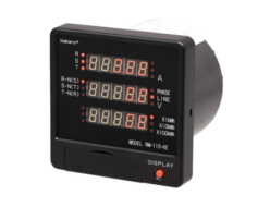
Hakaru DMH Digital Meter Relay: DC Ammeter, DC Voltmeter, Receiving Meter, AC Ammeter, AC Voltmeter
Manufacturer: HAKARU PLUS CORPORATION
Model: DMH
96 × 48, 4-Digit, Character Height 15mm, Indicator, Input–Alarm–Power Supply Isolation
Model
DMH-(1)-(2)-(3)-(4)
(1) Measurement Range
DC Input
| Code | Measurement Range |
|---|---|
| 02 | ±99.9mV |
| 03 | ±999.9mV |
| 04 | ±9.999V |
| 05 | ±99.9V |
| 06 | ±699.9V |
| 09 | 1 to 5V |
| V2 | 0 to 5V |
| 15 | ±99.9mA |
| 16 | ±999.9mA |
| 19 | 4 to 20mA |
AC Input
| Code | Measurement Range |
|---|---|
| 24 | 9.999Vrms |
| 25 | 99.99Vrms |
| 26 | 699.9Vrms |
| 36 | 999.9mArms |
| 37 | 5.000Arms |
(2) Power Supply
| Code | Description |
|---|---|
| A | AC100 to 240V |
| B | DC12 to 24V |
(3) Alarm Output
| Code | Description |
|---|---|
| No code | Relay contact output |
| TN | Open collector output, NPN |
(4) Display Color
| Code | Description |
|---|---|
| No code | Red LED |
| G | Green LED |
How to Order Example
Model: DMH-19-A
Special Specification:
Device Specifications
Exterior
Mounting: Panel-embedded type
Housing: Black plastic
Wiring connection: M3 screw terminal
Display / Input Section
Display contents: Current value, peak memory value, bottom memory value, or fluctuation width.
Numeric range: 0 to 9999, with zero suppression.
Display element: Red LED or green LED, character height 15mm.
Decimal point position: Front setting.
Negative input: “−” display.
Input overrange: Flashes at 130% display. However, when 9999 is exceeded, 0000 flashes.
For measurement range codes 06 and 26, when the input exceeds 699, the full-scale value flashes.
Scaling Function
Full-scale display: -9999 to +9999
Offset display: -999 to +999
For AC input, negative display is not available.
Sampling period: DC input 20 times/second, AC input 1 time/second.
Display period: DC input 50ms, 400ms, 1s, 2s, 4s, or 5s selectable.
Display period: AC input 1s, 2s, 4s, or 5s selectable.
Resolution: 1/1000
Input type: Single-ended
A/D conversion section: Sigma-delta conversion method
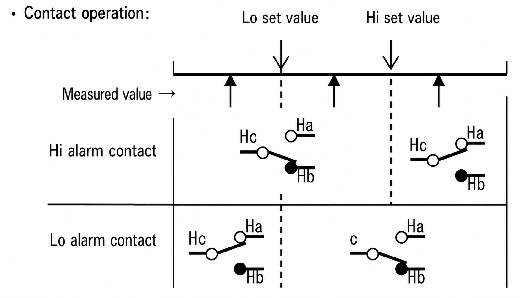
Alarm Function
Comparison input switching: Comparison judgment is performed using one of measured data, peak/bottom memory value, or fluctuation width data.
Setting digits: 4 numeric digits and 1 polarity digit.
Setting method: 2-point digital switch setting. Upper limit and lower limit can be set individually.
Hysteresis width setting: 1 to 999, 2-point independent setting.
Alarm display: HI, GO, and LO light up.
Output delay: ON delay, 0 to 60 seconds, 2-point independent setting in 1-second steps.
Comparison condition change: Equal GO judgment or equal NG judgment can be selected.
Standard Functions
Hold: Holds measured data, peak/bottom memory value, fluctuation width, and alarm output.
Reset: Resets the alarm output.
Zero set: Electrically sets the initial input value to zero.
When the 0% value of scaling is not 0, the value at zero setting becomes the 0% value.
Offset fixed: Fixes the 0% input to the 0% display value.
10⁰ digit display fixed: Fixes the 10⁰ digit display value to 0.
Peak / Bottom Memory and Fluctuation Width Function
Reset at power ON, measurement start, and power OFF.
Peak memory: Records the maximum measured value.
Bottom memory: Records the minimum measured value.
Fluctuation width memory: Records the peak value minus the bottom value.
Display selection function: Selects one from the current value, peak/bottom memory value, or fluctuation width.
Average Calculation Function
The display value is interval averaged or moving averaged within the display period.
| Display Period | Number of Measurement Data for Averaging |
|---|---|
| 50ms | No averaging |
| 400ms | 8 |
| 1s | 20 |
| 2s | 40 |
| 4s | 80 |
| 5s | 100 |
For moving average, the display period is fixed at 50ms.
The number of averaging data can be selected from 2, 4, 8, 16, or 32.
Cutoff function: Fixes the display to the 0% value of scaling.
Setting range: 0.1 to 19.9% input, for AC input.
Display fine adjustment: Fine adjustment of the display value is possible using the front switches.
Front Panel Function Description
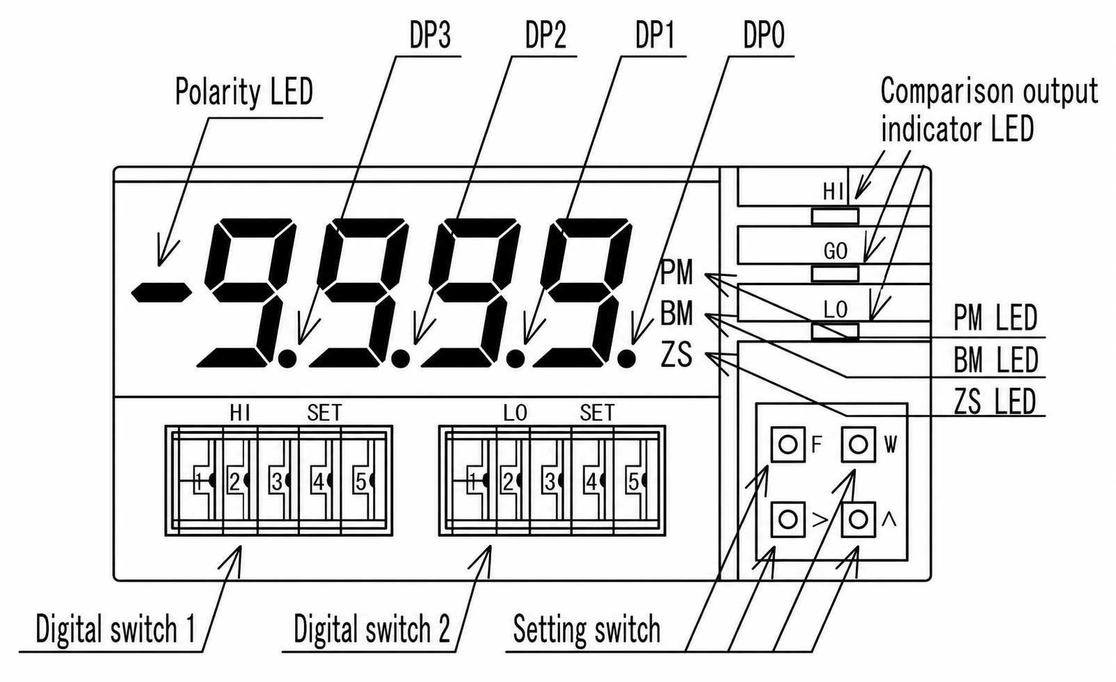
- F: Function switch, switches between measurement mode and setting mode.
- M: Mode switch, switches the display value and setting item.
- >: Shift switch, changes the setting digit and sends the setting value.
- ^: Up switch, selects setting contents and changes the setting value.
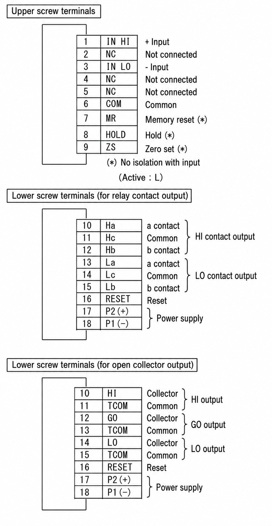
Input Specifications
Measurement Input
| Type | Measurement Range | Input Resistance | Overload |
|---|---|---|---|
| DC Input | 02 : ±99.9mV | 100MΩ | DC±250V |
| 03 : ±999.9mV | 100MΩ | DC±250V | |
| 04 : ±9.999V | 1MΩ | DC±250V | |
| 05 : ±99.9V | 1MΩ | DC±250V | |
| 06 : ±699.9V | 1MΩ | DC±700V | |
| 09 : 1 to 5V | 1MΩ | DC±250V | |
| V2 : 0 to 5V | 1MΩ | DC±250V | |
| 15 : ±99.9mA | 1Ω | DC±500mA | |
| 16 : ±999.9mA | 0.1Ω | DC±2A | |
| 19 : 4 to 20mA | 12.5Ω | DC±150mA | |
| AC Input | 24 : 9.999Vrms | 1MΩ | AC250V |
| 25 : 99.99Vrms | 1MΩ | AC250V | |
| 26 : 699.9Vrms | 1MΩ | AC700V | |
| 36 : 999.9mArms | 0.1Ω | AC2A | |
| 37 : 5.000Arms | 0.01Ω | AC7A |
Alarm Output Specifications
Relay Contact Output
Contact configuration: HI and LO, each 1c contact.
Contact capacity: AC250V 1A, resistive load.
Open Collector
Contact configuration: HI, GO, and LO, NPN output.
Contact capacity: DC30V 30mA, output saturation voltage DC1.6V or less.
Installation Specifications
Power supply:
- AC power supply: AC100 to 240V, 50/60Hz
- Power consumption: Approx. 4.5VA at AC100V, approx. 6VA at AC200V
- DC power supply: DC12 to 24V
- Current consumption: Approx. 150mA at DC12V, approx. 75mA at DC24V
Operating temperature range: 0 to 50°C
Storage temperature: -20 to 70°C
Dimensions: W96 × H48 × D91
Mass: Approx. 250g
Performance
Reference accuracy and temperature coefficient:
| Type | Measurement Range | Reference Accuracy Displayed as % of Reading Value |
|---|---|---|
| DC Input | 02 : ±99.9mV | ±(0.05% + 3digit) |
| 03 : ±999.9mV | ±(0.05% + 3digit) | |
| 04 : ±9.999V | ±(0.05% + 3digit) | |
| 05 : ±99.9V | ±(0.05% + 3digit) | |
| 06 : ±699.9V | ±(0.1% + 3digit) | |
| 09 : 1 to 5V | ±(0.1% + 3digit) | |
| V2 : 0 to 5V | ±(0.1% + 3digit) | |
| 15 : ±99.9mA | ±(0.1% + 3digit) | |
| 16 : ±999.9mA | ±(0.2% + 3digit) | |
| 19 : 4 to 20mA | ±(0.1% + 3digit) | |
| AC Input | 24 : 9.999Vrms | ±(0.2% + 10digit) |
| 25 : 99.99Vrms | ±(0.2% + 10digit) | |
| 26 : 699.9Vrms | ±(0.3% + 10digit) | |
| 36 : 999.9mArms | ±(0.5% + 20digit) | |
| 37 : 5.000Arms | ±(0.5% + 20digit) |
Response speed: The longer one between within 2 sampling cycles or within 1 display period.
Noise rejection ratio:
- Normal mode: 50dB or more, for DC input.
- Common mode: 110dB or more, for DC input.
- Power line mixed noise: AC power supply 1000V, DC power supply 500V.
Insulation resistance: DC500V, 100MΩ or more.
Dielectric strength:
- Between input terminal and external case: AC1500V for 1 minute.
- Between power supply terminal and external case: AC1500V for 1 minute.
- Between power supply terminal and input/output terminal: AC1500V for 1 minute.
- For DC power supply: AC1000V for 1 minute.
Connection Diagram
Outline Drawing (Unit: mm)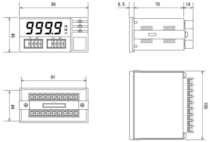
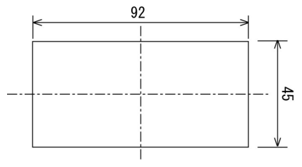
Mounting Dimensions Drawing (Unit: mm)
Related Products
REQUEST QUOTATION

PAYMENT

LINK


