Hakaru
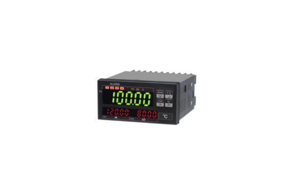
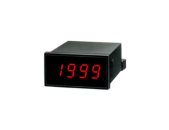
Hakaru DMXK Digital Meter Relay AC Ammeter, Voltmeter
Manufacturer: HAKARU PLUS CORPORATION
Model: DMXK
Scaling Meter, 96 × 48, 4-Digit, Character Height 15mm, Card Output–Power Supply Isolation
Model
DMXK-(1)-(2)-(3)-(4)-(5)
(1) Measurement Range
Voltmeter
| Code | Measurement Range |
|---|---|
| 22A | 99.99mVrms |
| 23A | 999.9mVrms |
| 24A | 9.999Vrms |
| 25A | 99.99Vrms |
| 26A | 699.9Vrms |
Ammeter
| Code | Measurement Range |
|---|---|
| 32 | 99.99µArms |
| 33 | 999.9µArms |
| 34 | 9.999mArms |
| 35 | 99.99mArms |
| 36 | 999.9mArms |
| 36 | 5.000Arms |
(2) Power Supply
| Code | Description |
|---|---|
| A | AC100 to 240V |
| B | DC12 to 24V |
| C | DC110V |
(3) Data Output 1
| Code | Description |
|---|---|
| No code | None |
| 09 | DC1 to 5V |
| 29 | DC4 to 20mA |
| BP | BCD output, TTL level, positive logic |
| BN | BCD output, TTL level, negative logic |
| DP | BCD output, transistor output, source type |
| DN | BCD output, transistor output, sink type |
| E0 | RS-232C |
| E1 | RS-485 |
| EC | External decimal point control |
(4) Data Output 2
| Code | Description |
|---|---|
| No code | None |
| E0 | RS-232C |
| E1 | RS-485 |
| EC | External decimal point control |
Note: Data Output 2 can be added only when Data Output 1 is 09 or 29.
(5) Comparison Output
| Code | Description |
|---|---|
| No code | Relay contact output |
| TN | Open collector output, NPN |
How to Order Example
Model: DMXK-36-A
Special Specification:
Device Specifications
Display Section
Numeric range: 0 to 9999
Main display: Red LED or green LED, character height 15.2mm
Sub display: 0 to 9999, red LED, character height 7.6mm
Decimal point position: Lights at any selected decimal point position.
Input overrange: When 9999 is exceeded, 0000 flashes.
For the 699.9V range, the full-scale value flashes when 699 is exceeded.
Scaling Function
Full-scale display: 0 to 9999
Offset display: 0 to 9999
Resolution: 1/10000
Hold
No isolation from input.
The display value, data output, current value, peak memory value, bottom memory value, fluctuation width, and comparison output are held. Active “L”.
Alarm Reset
No isolation from input.
The comparison output is restored. Active “L”.
Zero Reset
No isolation from input.
The input initial value is electrically set to zero. Active “L”.
Offset Fixed Display
When the input is below the offset value, the display is fixed to the offset display value.
10⁰ Digit Fixed Display
The display value of the 10⁰ digit is fixed to 0.
Sampling period: 2 times/second
Display period: 500ms, 1s, 2s, 4s, or 5s selectable.
Average Calculation
The display value is averaged by interval average or moving average within the display period.
| Display Period | Number of Measurement Data for Averaging |
|---|---|
| 500ms | No averaging |
| 1s | 2 |
| 2s | 4 |
| 4s | 8 |
| 5s | 10 |
For moving average, the display period is fixed at 500ms.
The number of moving-average measurement data can be selected from 2, 4, 8, 16, or 32.
Response: The longer one between within 2 sampling cycles or within the display period.
Input type: Single-ended floating input
A/D conversion section: Sigma-delta conversion method
Unit seal: Included
Input Specifications
Input resistance and overload:
| Type | Measurement Range | Input Resistance | Input Overload | Terminal No. |
|---|---|---|---|---|
| Voltmeter | 22A : 99.99mVrms | 100kΩ | AC10V | ①-④ |
| 23A : 999.9mVrms | 100kΩ | AC100V | ①-④ | |
| 24A : 9.999Vrms | 1MΩ | AC400V | ①-④ | |
| 25A : 99.99Vrms | 1.9MΩ | AC400V | ②-④ | |
| 26A : 699.9Vrms | 1.9MΩ | AC700V | ③-④ | |
| Ammeter | 32 : 99.99µArms | 1kΩ | AC20mA | ①-④ |
| 33 : 999.9µArms | 100Ω | AC50mA | ①-④ | |
| 34 : 9.999mArms | 10Ω | AC150mA | ①-④ | |
| 35 : 99.99mArms | 1Ω | AC500mA | ②-④ | |
| 36 : 999.9mArms | 0.1Ω | AC2A | ②-④ | |
| 36 : 5.000Arms | 0.01Ω | AC10A | ③-④ |
Analog Output Specifications
Allowable error: ±0.15%
Temperature coefficient: 200ppm/°C
Resolution: 1/10000
Output period: 500ms
Output response: Within 1s for input.
0 to 90% response, when display period is 500ms and average calculation is not used.
| Output Range | Output Impedance | Allowable Load Resistance |
|---|---|---|
| DC1 to 5V | 0.1Ω or less | 500Ω or more |
| DC4 to 20mA | 5MΩ or more | 600Ω or less |
BCD Output Specifications
TTL Level Output
Data output: Parallel BCD code, 1-2-4-8, latch output
TTL level: C-MOS compatible, Fo = 2
Control output:
Overrange (OVER): Logic “1” during overrange
Synchronization signal (SYNC): 10ms “L” pulse
Control input:
Latch: Active “L”
Memory function: Active “L”
Data inhibit: Active “H”
Transistor Output
Output capacity: DC30V, 30mA max.
Data output: Parallel BCD code, 1-2-4-8, latch output
“1” output: Transistor ON
Control output:
Overrange (OVER): Transistor ON during overrange
Synchronization signal (SYNC): 10ms ON
Control input:
Latch: Active ON
Memory function: Active ON
Data inhibit: Active OFF
Serial Communication
RS-232C, RS-485
Transmission method: Asynchronous half-duplex method
Communication speed: 4800, 9600, 19200, 38400bps
Transmission code: Conforms to JIS 8-unit code
Data format:
Data bit length: 7 bits or 8 bits
Stop bit length: 2 bits or 1 bit
Parity check: Even, odd, or none
Error detection: Vertical parity and BCC
Comparison Judgment Function
Comparison digits: 4 numeric digits
Comparison target switching: Comparison judgment can be performed using one of the current value, peak memory value, bottom memory value, or fluctuation width data.
Comparison method: 4-point independent setting, CPU comparison judgment method
Setting method: Upper/lower limit setting method or zone setting method can be selected.
Upper/lower limit setting: 4-point independent setting, upper/lower limit optional setting, Hi, Lo, or OFF, equal judgment or unequal judgment switching included.
Zone setting: Judgment is performed for each section of the 4 independently set values.
Setting condition: AL4(HH) > AL3(H) > AL2(L) > AL1(LL)
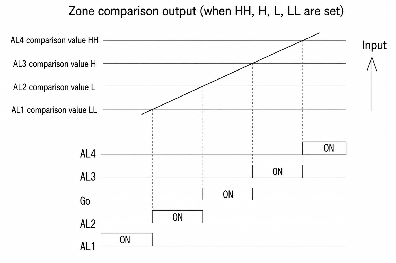
Hysteresis function: Hysteresis width 1 to 999, 4-point independent setting. Disabled during zone judgment.
Comparison display: AL1 to AL4 red LED display
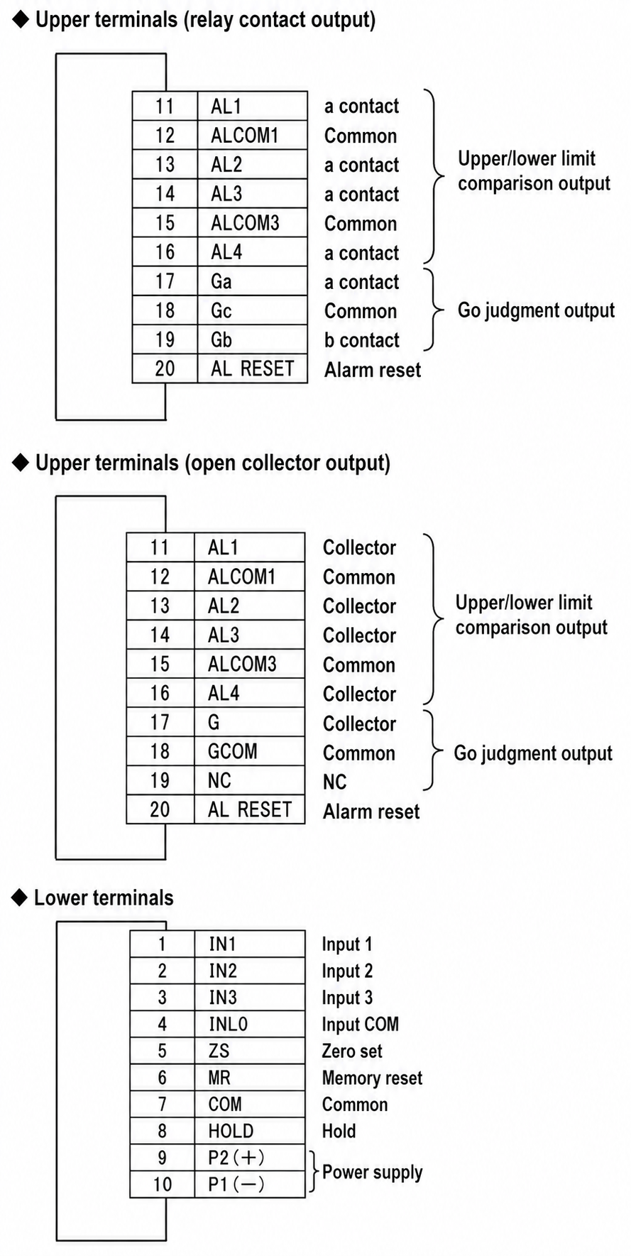
Comparison Output
Relay contact output:
AL1 to AL4, one contact each. Common is shared by AL1 and AL2, and shared by AL3 and AL4.
Go: 1c contact
Contact capacity: AC250V, 1A
Resistive load: DC30V, 1A
Open collector output, NPN:
AL1 to AL4, Go
Output rating: DC30V, 30mA max.
Output saturation voltage: DC1.6V or less
Output delay: ON delay 0 to 99 seconds, freely set in 1-second steps. Common setting for 4 points.
Alarm reset function: Restores the comparison output. No isolation from input.
Power-on delay: Comparison judgment output OFF for approx. 4 seconds after power is turned on and within the specified time.
Setting range: 4 to 99 seconds, freely set in 1-second steps.
Installation Specifications
Power supply: AC100 to 240V, 50/60Hz, DC12 to 24V, DC110V
Allowable power supply voltage range: AC90 to 250V, DC9 to 32V, DC90 to 170V
Power consumption:
| Power Supply | Power Consumption |
|---|---|
| AC100V | Approx. 9VA |
| AC200V | Approx. 11.5VA |
| DC12V | Approx. 400mA |
| DC24V | Approx. 200mA |
| DC110V | Approx. 40mA |
Operating temperature range: 0 to 50°C
Storage temperature: -20 to 70°C
Mass: Approx. 300g
Protective structure: Front panel section equivalent to IP65
Performance
Noise rejection ratio: Power line mixed noise 1000V
Insulation resistance: DC500V, 100MΩ or more
Dielectric strength:
Between input and external case: AC2000V for 1 minute
Between power supply and external case: AC2000V for 1 minute
Between power supply and input/output: AC1500V for 1 minute
Between input/output and power supply: AC500V for 1 minute
Reference Accuracy
| Type | Measurement Range | Accuracy |
|---|---|---|
| Voltmeter | 22A : 99.99mVrms | ±(0.2% + 10digit) |
| 23A : 999.9mVrms | ±(0.2% + 10digit) | |
| 24A : 9.999Vrms | ±(0.2% + 10digit) | |
| 25A : 99.99Vrms | ±(0.3% + 10digit) | |
| 26A : 699.9Vrms | ±(0.3% + 10digit) | |
| Ammeter | 32 : 99.99µArms | ±(0.3% + 10digit) |
| 33 : 999.9µArms | ±(0.3% + 10digit) | |
| 34 : 9.999mArms | ±(0.3% + 10digit) | |
| 35 : 99.99mArms | ±(0.5% + 10digit) | |
| 36 : 999.9mArms | ±(0.5% + 10digit) | |
| 36 : 5.000Arms | ±(0.5% + 10digit) |
Connection Diagram
Option, Middle Section
Analog Output
Screwless terminal
| C1 | C2 |
|---|---|
| + OUT | − OUT |
BCD Output
| Function Name | Pin No. | Function Name | |||
|---|---|---|---|---|---|
| 10¹ | 1 | 1 | 18 | 1 | 10⁰ |
| 2 | 2 | 19 | 2 | ||
| 4 | 3 | 20 | 4 | ||
| 8 | 4 | 21 | 8 | ||
| 10³ | 1 | 5 | 22 | 1 | 10² |
| 2 | 6 | 23 | 2 | ||
| 4 | 7 | 24 | 4 | ||
| 8 | 8 | 25 | 8 | ||
| NC | 9 | 26 | 1 | 10⁴ | |
| 10 | 27 | 2 | |||
| 11 | 28 | 4 | |||
| 12 | 29 | 8 | |||
| 13 | 30 | MEMORY RESET | |||
| OVER | 14 | 31 | OUTPUT ENABLE | ||
| SYNC | 15 | 32 | LATCH | ||
| BOTTOM MEMORY | 16 | 33 | PEAK MEMORY | ||
| DATA COM | 17 | 34 | DATA COM | ||
RS-232C or RS-485
Screwless terminal
| C3 | C4 | C5 | C6 | C7 | |
|---|---|---|---|---|---|
| RS-232C | SD | RS | RD | CS | SG |
| RS-485 | Terminator | NC | + | − | |
Analog Output + RS-232C or RS-485
Screwless terminal
| C1 | C2 | C3 | C4 | C5 | C6 | C7 | |
|---|---|---|---|---|---|---|---|
| RS-232C | + OUT | − OUT | SD | RS | RD | CS | SG |
| RS-485 | + OUT | − OUT | Terminator | NC | + | − | |
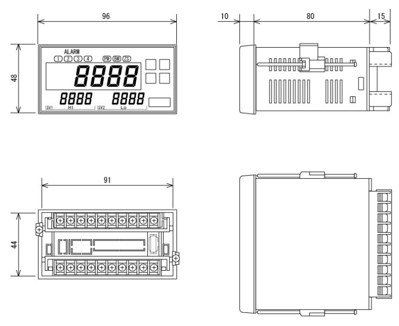
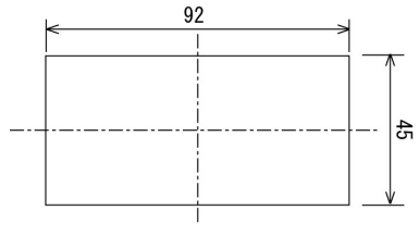
Outline Drawing (Unit: mm)
Terminal Arrangement Diagram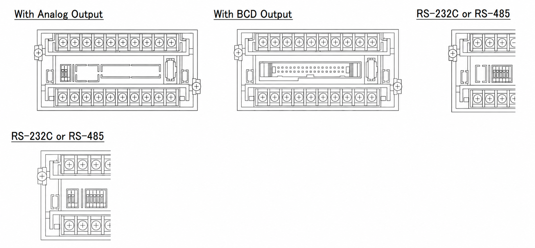
Mounting Dimensions Drawing (Unit: mm)
Related Products
-
Hakaru DPA9–A Digital Panel Meter: DC Ammeter, Voltmeter, And Receiver
-
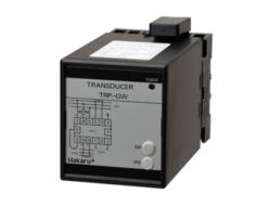
Hakaru TRP-GW Power Transducer Analog Output Type
-
Hakaru RRF-G Rectangular (83 x 83) Frequency Meter (Transducer Type)
-
Hakaru RAC-12W Rectangular (122 x 122)
-
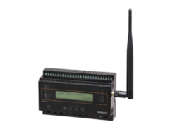
Hakaru HLR-A4C4 LoRa Wireless Multi-Function 4-Point Model
-
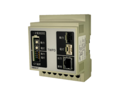
Hakaru TWPD Total Lighting And Power Combined Electric Energy Converter
REQUEST QUOTATION

PAYMENT

LINK


