Japan, KONAN ELECTRIC, Limit Switch Box
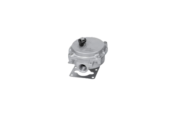
KONAN TA2-SB2 Limit Switch Box (Made of Aluminum)
Product Made In Japan
Manufacturer: KONAN ELECTRIC
Model: TA2-SB2
When placing orders with only options of actuators with options in the preceding sections and other options, use them.
Assembly of the TA2 options with fitting bolts, piping joints, packing, etc. are available on request.
Specifications
| Model code | TA2-SB2 | Connection diagram | NO Type (Standard) NC Type | |||||||
| Rating of the limit switch | Rated voltage (V) | Non-inductive Load (A) | Inductive Load (A) | 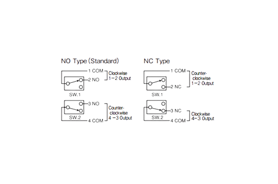 (These diagrams show the connection rotated clockwise.) Loosen terminal strips, insert lead wires at correct positions securely, then ensure to tighten screws. (These diagrams show the connection rotated clockwise.) Loosen terminal strips, insert lead wires at correct positions securely, then ensure to tighten screws.Applicable lead wire 2.5mm- Terminal screw size M3 * Lead wire conduit G1/2z Connect the gland wire to the grand terminal as needed. | ||||||
| AC 125 | 11 | 7 | ||||||||
| AC250 | 11 | 7 | ||||||||
| DC 125 | 0.5 | — | ||||||||
| DC250 | 0.25 | — | ||||||||
| Operating temperature | — 5 — 60°C (only switch box itself) | |||||||||
| Voltage proof | AC 1500V (for one minute) | Body material | ADC | |||||||
| Protection class | IP65 | Mass | Refer to Page 98. | |||||||
| Paint color | Silver | |||||||||
Model Code
1 Spindle Size Table
| TA2-0402D (R/L) | 9 |
| TA2-050D (R/L) TA2-063D (R/L) | 11 |
| TA2-080D (R/L) TA2-100D (R/R2/L/L2) | 16 |
| TA2-125D (R/R2/L/L2) TA2-160D (R/R2/L/L2) | 22 |
2 Output Signal Table
| NO Type (Standard) | NO |
| NC Type | NC |
3 With/Without Gland Table
| Without Gland (φ) | No Entry |
| φ 8.5 ~ φ 9.4 | 15A |
| φ 9.5 ~ φ 10.4 | 15B |
| φ 10.5 ~ φ 11.4 | 15C |
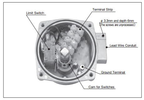
Switch Box Internal Configuration
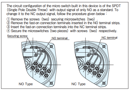
Change of the Output Signal of the Switch
Related Products
-
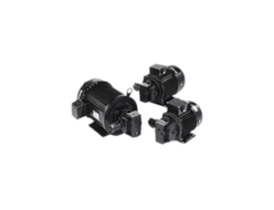
Nachi UVN Series Unipump
-
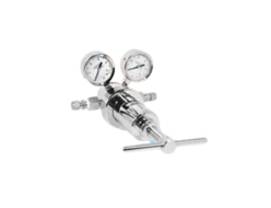
Chiyoda Seiki SKR-200H/SKR-200H-H/MR-200H/MR-200H-H/SKR-200HS/SKR-200HS-H/MR-200HS/MR-200HS-H (Primary pressure: 24.6 MPa or less / adjustment pressure 2.0 to 20.0 MPa)
-
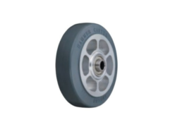
Hammer Caster 435SOS-ARB Rubber Wheel
-
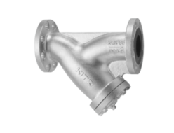
Kitz 20FDY Ductile Iron 20K Strainer for Gas Service
-

Eisen SS Series Pin Gauge
-
Eagle Jack (Konno Corporation) SDL-20F Smart Dolly
REQUEST QUOTATION

PAYMENT

LINK


