Toyo Keiki
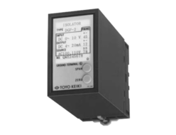
Toyo Keiki NGM Series Power Factor Transducer
Product Made In Japan
Manufacturer: Toyo Keiki
Model: NGM Series
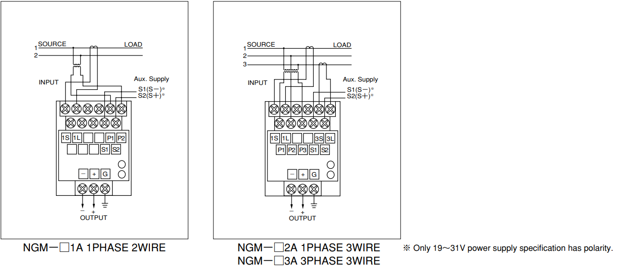
NGM-□1A : 1phase 2wire
NGM-□2A : 1phase 3wire
NGM-□3A : 3phase 3wire
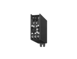
Lighter because plastic is used for casing.
Improved reliability and greater compactness through the use of custom ICs.
JIS C 1111 AC/DC transducer 3.0 class.
Specification
| INPUT | ||||||
|---|---|---|---|---|---|---|
| KIND | MARK | INPUT | RATED VOLT. | RATED CUR. | FREQUENCY | CONSUMPTION WATT |
| 1φ2W NGM-□1A | 01 | LEAD 0.5 ~ 1 ~ LAG 0.5 | 100V | 5A | 50Hz | Voltage input : 0.5VA at 1 element Current input : 0.5VA at 1 element Note : 1. 1 phase 2 wire and 1 phase 3 wire devices are set for a frequency of either 50Hz or 60Hz. 3 phase line devices can operate at either 50Hz or 60Hz. 2. It is necessary to balance the voltage circuits of 3 phase 3 wire devices. However, the current will behave normally if the circuits are not balanced |
| 02 | LEAD 0.5 ~ 1 ~ LAG 0.5 | 100V | 5A | 60Hz | ||
| 11 | LEAD 0.5 ~ 1 ~ LAG 0.5 | 200V | 5A | 50Hz | ||
| 12 | LEAD 0.5 ~ 1 ~ LAG 0.5 | 200V | 5A | 60Hz | ||
| 99 | OTHER | |||||
| 1φ3W NGM-□2A | 01 | LEAD 0.5 ~ 1 ~ LAG 0.5 | 2 x 100V | 5A | 50Hz | |
| 02 | LEAD 0.5 ~ 1 ~ LAG 0.5 | 2 x 100V | 5A | 60Hz | ||
| 11 | LEAD 0.5 ~ 1 ~ LAG 0.5 | 2 x 200V | 5A | 50Hz | ||
| 12 | LEAD 0.5 ~ 1 ~ LAG 0.5 | 2 x 200V | 5A | 60Hz | ||
| 99 | OTHER | |||||
| 3φ3W NGM-□3A | 21 | LEAD 0.5 ~ 1 ~ LAG 0.5 | 110V | 5A | 50/60Hz | |
| 31 | LEAD 0.5 ~ 1 ~ LAG 0.5 | 220V | 5A | 50/60Hz | ||
| 99 | OTHER | |||||
| WORKING RANGE Rated voltage range : 60V—240V Current range : 0.1 A—5A Frequency range : 45Hz—450Hz Input range for working range : LEAD 0.5—1 —LAG 0.5 or LAG 0.5—1 —LEAD 0.5 | ||||||
| OUTPUT | |||||
|---|---|---|---|---|---|
| MARK | OUTPUT | LOAD RESISTANCE | WORKING RANGE | ||
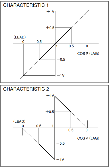
| 1 | -100 – 0 – + 100 mV | 600 Ω ~ ∞ | Max. voltage output: 10V, Loading current: below 10mA Max. current output: 20mA, Loading voltage: below 11V Relationship between input and output: Lead side input for minus output and Lag side input for positive output are standard. We can also make items that allow Lag side input for minus output and Lead side input for positive output. We can also produce items that at LEAD 0.5—1—LAG 0.5 have —50%–Z+100%—F50% characteristics. | ||
| 2 | – 1 – 0 – + 1 V | 600 Ω ~ ∞ | |||
| 3 | – 5 – 0 – + 5 V | 2k Ω ~ ∞ | |||
| 4 | – 10 – 0 – + 10 V | 5k Ω ~ ∞ | |||
| 5 | 1 – 3 – 5 V | 2k Ω ~ ∞ | |||
| 6 | 1 – 0 – + 1 mA | 0 ~ 10k Ω | |||
| 7 | – 10 – 0 – + 10 mA | 0 ~ 1k Ω | |||
| 8 | 4 – 12 – 20 mA | 0 ~ 550 Ω | |||
| 9 | OTHER OUTPUT | ||||
| AUXILIARY POWER SUPPLY | ||
|---|---|---|
| MARK | USE RANGE | CONSUMPTION WATT |
| 1 | DC 19V—31V | approx. 3 W |
| 4 | AC 80V-264V 50/60Hz DC 80V-143V | approx. 4 VA approx. 3 W |
| 9 | OTHER | |
| 0 | NO ASSIST POWER SUPPLY (SELF POWER SUPPLY) | |
Power factor transducer may have the two types of characterristics shown below.
If no preference is specified characteristics will be as shown in 1.
SPECIFIC CHARACTER
(1) Tolerance
±3% of output span. (Ambient temperature 23 ℃)
(2) Effect of temperature
Within ±0.5% of output span. (For 23 ℃±10℃ variations)
(3) Effect of auxiliary power supply
Within ±0.25% of output span. (For rated voltage ±10% variations)
(4) Effect of frequency
Within ±1.5% of output span. (For standard frequency ±5%
variations)
(5) Effect of input voltage
Within ±1.5% of output span. (For standard vortage ±10%
variations)
(6) Effect of input current
Within ±3% of output span. (For 20%-120% rated current variations)
(7) Effect of load resistance
Within ±0.05% of output span. (For load resistance range)
(8) Output ripple
Within 1%p-p of output span.
(9) Response time
Shorter than 1sec. (Time to 99% output)
(10) Dielectric strength
2000V AC,1min.(50/60Hz)
(Between input, output, auxiliary power and external case)
(11) Insulation resistance
Higher than 100MΩ at 500V megger.
(Between input, output, auxiliary power and external case)
CONNECTION DIAGRAM
DESIGNATION ITEM AT ORDER
| 1. TYPE AND AUXILIARY POWER SUPPLY | 2. INPUT | 3. OUTPUT |
|---|---|---|
| NGM-□ □ A | -□ | -□ |
ORDER EXAMPLE
① NGM-43A-21-8
② NGM-43A-99-8 INPUT : LEAD 0.5~1~LAG 0.5,115V,5A
※Power factor measurement in circuits that have tidal currents
The effectuve measurement range of NGM type power factor transducers is LEAD 0.5~1~LAG 0.5.
Does not operate normally during backward tidal current(the current supply and receeipt flow are reversed).
To provide power factor measurements in circuits with a tidal flow the NGM-□RA type is available.
REQUEST QUOTATION

PAYMENT

LINK


