Chino, Japan
Chino IR-FA Series Fiber Type Radiation Thermometer

Made in Japan
Manufacturer: Chino Corporation
Model: IR-FA Series
Thermometer Models
| Types | Detecting Elements | Models |
|---|---|---|
| For low temperature | Cooling type PbS | IR-FACR |
| For medium to high temperature | Cooling type PbS | IR-FAI |
| InGaAs Si | IR-FAS | |
| Two-color type | InGaAs/InGaAs | IR-FAQI |
| Si/Si | IR-FAQS | |
| Si/InGaAs | IR-FAQH |
Lens Assembly Models
Core diameter 400μm
| Lens Assembly Measuring Distance and Measuring Diameter | Lens Assembly Measuring Distance and Measuring Diameter |
|---|---|
| φ1mm at 100mm | IR-FL0□□□□ |
| φ12mm at 1000mm | IR-FL1□□□□ |
| φ5mm at 500mm | IR-FL2□□□□ |
| φ2mm at200mm | IR-FL3□□□□ |
| φ4mm at200mm | IR-FL4□□□□ |
| φ5mm at150mm | IR-FL5□□□□ |
| φ20mm at600mm | IR-FL6□□□□ |
| φ8mm at1000mm | IR-FL8□□□□ |
Core diameter 800μm (For low temperature)
| Lens Assembly Measuring Distance and Measuring Diameter | Models |
|---|---|
| φ10 at150mm | IR-FL5□□□□ |
| φ40 at600mm | IR-FL6□□□□ |
| φ13 at200mm | IR-FL7□□□□ |
Power Supply Unit Model
| Name | Model |
|---|---|
| Power supply unit | IR-ZFEP |
Features
IR-FA series is an optical fiber transmission type radiation thermometer. Measurement light (radiant energy) captured by a size of a pinky, small lens assembly is led to a detecting element stored in a small box type thermometer. With small lens assembly and flexible optical fiber transmission, this thermometer is useful for measurements of a place where direct view is impossible or a narrow place, and a place where inductive interference occurs electrically.
- Optical fiber can be used without cooling up to 150°C.
- Optical fiber does not have electrical conduction so it is applicable for induction heating and explosion proof atmosphere.
- Laser targeting option is available for checking measuring point.
- Thermometer is compact, light weight, and DIN rail installation available.
- For low temperature, for medium to high temperature, and two-color type etc. various types are available.
Standard Temperature Range
| Types | Detecting Elements | Measuring Range | Lens assembly |
|---|---|---|---|
| Single-color type | Cooling type PbS | 70 to 250°C 100 to 300°C | IR-FL5□, IR-FL6□, IR-FL7□(Core diameter 800μm) |
| 250 to 800°C | IR-FL0□, IR-FL1□, IR-FL2□, IR-FL3□, IR-FL4□(Core diameter 400μm) | ||
| 150 to 500°C 250 to 800°C | IR-FL5□, IR-FL6□(Core diameter 400μm) | ||
| 300 to 800°C | IR-FL8□ | ||
| InGaAs | 150 to 450°C 200 to 700°C 250 to 1000°C 300 to 1300°C | IR-FL5, IR-FL6 | |
| 250 to 1000°C 300 to 1300°C 350 to 1600°C | IR-FL0, IR-FL1, IR-FL2, IR-FL3, IR-FL4, IR-FL8 | ||
| Si | 400 to 900°C 500 to 1200°C 600 to 1800°C 700 to 2400°C | IR-FL5, IR-FL6 | |
| 600 to 1800°C 700 to 2400°C 800 to 3000°C | IR-FL0, IR-FL1, IR-FL2, IR-FL3, IR-FL4, IR-FL8 | ||
| Two-color type | InGaAs/InGaAs | 300 to 1200°C 400 to 1500°C | IR-FL5, IR-FL6 |
| 400 to 1500°C | IR-FL0, IR-FL1, IR-FL2, IR-FL3, IR-FL4 | ||
| 450 to 1500°C | IR-FL8 | ||
| Si/Si | 800 to 1600°C 1000 to 2000°C | R-FL0, IR-FL1, IR-FL2, IR-FL3, IR-FL4, IR-FL5, IR-FL6 | |
| 850 to 1600°C 1000 to 2000°C | IR-FL8 | ||
| Si/InGaAs | 600 to 1500°C 700 to 2000°C 800 to 2400°C 1000 to 3000°C | IR-FL0, IR-FL1, IR-FL2, IR-FL3, IR-FL4, IR-FL5, IR-FL6, IR-FL8 |
Specifications
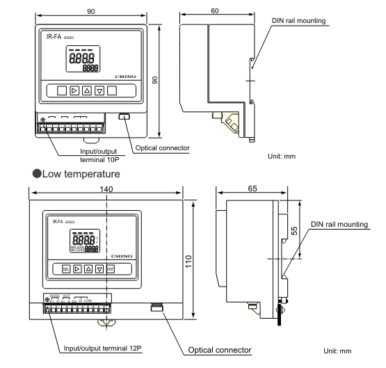
Thermometer
| Models | IR-FAC | IR-FAI | IR-FAS | IR-FAQI | IR-FAQS | IR-FAQH | |
|---|---|---|---|---|---|---|---|
| Measuring System | Single-color type | Two-color type | |||||
| Detecting Elements | Cooling type PbS | InGaAS | Si | InGaAs/InGaAs | Si/Si | Si/InGaAs | |
| Measuring Wavelength | 2.0μm | 1.55μm | 0.9μm | 1.55/1.35μm | 0.85/1.00μm | 1.55/0.9μm | |
| Accuracy Rating | 70°C or more, below 300°C: ±4°C 300°C or more, below 500°C: ±5°C 500°Cor more: ±1.0% of measured value | Below 1000°C: ±5°C 1000°C or more, below 1500°C: ±0.5% of measured value 1500°C or more, below 2000°C: ±1% of measured value 2000°C or more: ±2% of measured value | |||||
| Repeatability | Within 2°C | 0.2°C | |||||
| Temperature Drift | 0.2°C/°C | 0.1°C or 0.015%/°C of measured value, whichever larger | 0.2°C/°C or 0.02%/°C of measured value, whichever larger | ||||
| Resolution | 70°C or more, below 100°C: Approx. 3°C, 100°C or more, below 200°C: Approx. 2°C, 200°C or more: Approx. 0.5°C | 0.5°C | 1.0°C | ||||
| Response Time | 0.01s | 0.04s | |||||
| Emissivity (Ratio) Compensation | Emissivity set value: 1.999 to 0.050 *1 | Emissivity set value: 1.999 to 0.050 | Emissivity set value (ratio): 1.999 to 0.050 | ||||
| Signal Modulation | DELAY: Average value tracing (smoothing) (Modulation degree 0.0 to 99.9s, 0.1s step can be set freely), Modulation degree 0=REAL, PEAK: Max. value tracing (Modulation degree 0, 2, 5, 10°C/s selection), Modulation degree 0=Peak hold) | ||||||
| Display System | LCD 4-digit (Temperature display, parameter display) | ||||||
| Analog Output | 4 to 20mA DC Isolated output (Load resistance 500Ω or lower) Accuracy rating: ±0.2% of output range Output resolution: 0.01% of output range Output scaling: It can be set freely within the measuring temperature range. Dummy output: It can be set freely within the range of 0 to 100% of analog output. | ||||||
| Contact Output | 2-point, select from high, low, high-high, low-low alarms, or error signal Photo-coupler 30V DC, Max. 50mA | 1-point, high (low) alarm or error signal Photo-coupler 30V DC, Max. 50mA | |||||
| Contact Input | 1-point, peak hold or sample hold, dry contact or open collector | ||||||
| Parameter Settings by Keys | Operator mode: Setting of emissivity, signal modulation, alarm and others Engineering mode: Setting of output scaling, ZERO/SPAN, automatic emissivity calculation: input of reference temperature, output correction and others including option-related-parameters | Operator mode: Setting of emissivity, signal modulation, alarm and others Engineering mode: Setting of output scaling, ZERO/SPAN, automatic emissivity calculation: input of reference temperature, output correction and others including option-related-parameters | |||||
| Calculation Function | ZERO/SPAN adjustment, Automatic emissivity calculation *2, Output correction | ZERO/SPAN adjustment, Automatic emissivity calculation, Output correction | ZERO/SPAN adjustment, Automatic emissivity calculation, Output correction | ||||
| Self-Diagnosis | Thermometer temperature abnormal, parameter error | ||||||
| Option | Laser Targeting | Built-in semi conductor laser floodlight, laser beam 1mW or less (645nm) class 2, (Built-in semi conductor laser floodlight is not available for High-sensitivity type) | |||||
| Analog Input | Input signal: 4 to 20mA Select remote emissivity programming or automatic emissivity calculation input of reference temperature. | Input signal: 4 to 20mADC Select remote emissivity programming or automatic emissivity calculation input of reference temperature. | |||||
| Communication Interface | RS-485 Sending of measured data (up to 1-digit below decimal point), and sending/receiving of parameters | ||||||
| Working Temperature Range | 5 to 40°C | 0 to 50°C | |||||
| Rated Power Supply Voltage | 24V DC(allowable voltage fluctuation range to 28V DC) | ||||||
| Power Consumption | Max. 15VA | Max. 3VA (Approx. 130mA) | |||||
| Connection | Cramp type no-screw terminals | ||||||
| Installation Method | DIN-rail installation or wall installation | ||||||
| Case/Material | Copper board | Resin | |||||
| External Dimensions/Weight | W140×H110×D65mm, Approx. 1.0kg (Thermometer only) | W90×H90×D60mm, Approx. 250g (Thermometer only) | |||||
| CE Marking Conformity | Conforms to CE marking (EMC directive:EN5501 Group 1 Class A, EN50082-2) | ||||||
*1 Correction effective ranges are ε≒1.0 to 0.8 for measured temperature 70 to 80°C and ε≒1.0 to 0.6 for 80 to 90°C.
*2 Emissivity (ratio) is calculated automatically by input reference input temperature through key setting or option analog input.
Fiber optics
| Core diameter 400μm | Core diameter 800μm (For low temperature type only) | |
| Fiber | Single core quartz fiber | |
| Sheath |
| |
| Working Temperature | 0 to 150°C |
|
| Length | For low temperature type・・・2m, 4m, 5m For medium to high temperature・Two-color types・・・2m, 4m, 5m, 10m, 15m, 20m | 2m |
| Allowable Bending Radius | R100mm | R150mm |
Related Products
-
Kondotec EE Series Eye & Eye Turnbackle
-
Watanabe AL-512 2-wire digital Panel Meter for Process Signals – 2-wire Meter
-
TONE RH3FHL Long Ratchet Handle, Flex Head (Socket Hold Type)
-
Organo Clean Filter A Pool Filtration Equipment
-
Seiwa E04RM201010 RC, RM and RMX Types Non-split Cores
-
UHT CORPORATION FP Series Flexible Substrate Punching Machine


