Toyo Keiki
TOYO KEIKI MPV-11 and MPC-12 Earth-resistance Meter Relay
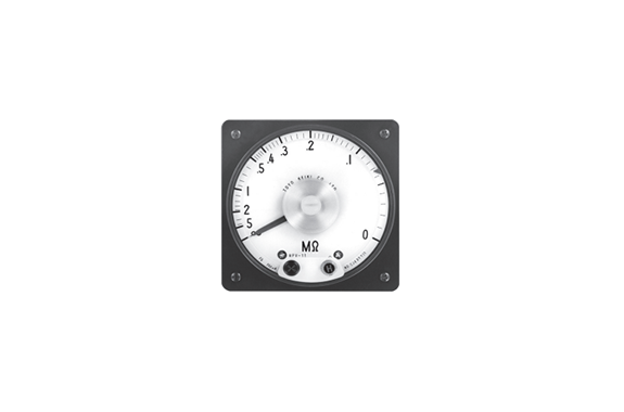
Product Made In Japan
Manufacturer: Toyo Keiki
Model: MPV-11 and MPC-12
Overview
This meter relay can measure the earth resistance value of a contactless AC circuit while also detecting abnormal earth resistance values in the same circuit. Comprising a contactless meter relay and an extra power unit, this meter relay can be used for a wide range of purposes such as detecting abnormalities in grounding accidents in settings such as boats.
A particularly useful feature is the fixed voltage circuit built into the extra power unit, which maintains a roughly fixed voltage circuit even during fluctuations of ±10% in the input voltage of AC115V, preventing measurement error.
Features
● Earth resistance measurements can be taken continuously while also setting and detecting the desired earth resistance values on the scale of the photoelectric-type detection setting mechanism, as well as activating warning equipment using the relay circuit contact.
● Lines can be measured and detected while live.
Specification
| Meter Relay | MPV-11 | MPC-12 | Note | |
|---|---|---|---|---|
| Outside (mm) | 110×110 | 120×110 | Intrinsic Error: Indicated value ±5% Between 0.05-1 MQ ±10% • Extra Power Unit RG-3 • Meter Sensitivity DC250pA | |
| Scale Length (mm) | Approx. 170 | Approx. 100 | ||
| Accuracy Class | — | — | ||
| Pointer | Tapered Type | Wand Type | ||
| Set Pointer | Triangular with Red H | Wand Type with Red H | ||
| Scale Plate | White Base | |||
| Scale Division | ||||
| Mounting Posture | Vertical | |||
| Cover | Methacrylic Resin | Special Anti-electric Resin | ||
| Base | • Between Terminals – Phenol Resin • Body Cover – ABS resin | |||
| Cover Coating Color | N -1.5 (black) or 7.5B G4/1.5 (blue-green) | |||
| Setting | H Setting (Single Side Only) | |||
| Operating Error for Setting Value (Against Scale Length) | 1.5 | 1.5 | ||
| Dead Band | 1.0 | 1.0 | ||
| Note 1) Meter Action | Stop Type | — | — | |
| Passage Type | o | o | ||
| Auxiliary Power Supply | AC | AC 110V, AC115V, AC220V | ||
| Note 2) Output Signal | Retaining Type | o | o | |
| Instantaneous Type | — | — | ||
| Output Contact Arrangement and Capacity | lab, AC220V, 3A | lab, AC100V, 1A | ||
| Insulation Test | Between electrical circuit and outer casing of meter: 1OMQ or more for 500V mega | |||
| Voltage Test | Between electrical circuit and outer casing of meter: AC 1500V (5O/6OHz per minute) Between contact relay circuit and other electrical circuits: AC 500V (5(V60Hz per minute) | |||
| Characteristics of Meter | Characteristics of the meter part are based on JIS C 1102-1 to 9 | |||
Note 1) Meter Action: Passage Type – The pointer can pass to the end
of the scale even if it exceeds the
setting value.
Note 2) Output: Retaining Type – Output is retained even when the pointer passes the setting value.
The output is discarded when the pointer goes back below the setting value.
Note 3) Others:
a) DC circuit type can also be manufactured
b) See the page about our contactless meter relay for details.
c) In particular, a standard meter type can be manufactured if the detection equipment is not required.
d) Also includes a converter.
Type I S-3: For 3P
Type I S-1: For 1P
Operating Principles
Apply an AC power supply to the extra power unit to generate DC50V on the output side.
This DC power supply can be used to combine the unit with a DC ammeter with an MΩ scale, making it possible to take measurements and read earth resistance for circuit currents that change depending on the ground status.
The AC side and output side of the extra unit are insulated by a transformer. This means that the DC power supply can be considered separate from the lines, creating the basic circuit shown on the left.
In the circuit diagram on the left, DC50V is being generated by the power unit, the power is connected to the meter in a series where Rs = 0.2 MΩ (scale centering on meter), and a resistance value is being indicated.
When switch S is turned on, the pointer of the meter moves to the maximum, indicating 0MΩ in this case
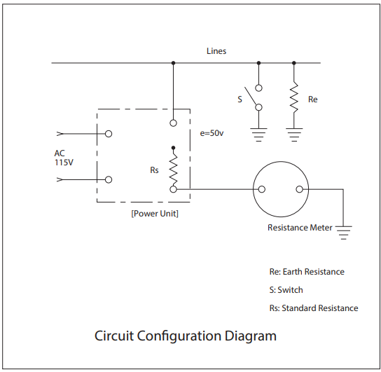
This means that the maximum current sensitivity value of the inflow current is :

If a grounding accident occurs and the earth resistance is 0.2 MΩ (Re = 0.2 MΩ), the inflow current:

and the center scale point of 0.2 MΩ is indicated.
The relationship between the earth resistance value and the current i is as shown below.
Outside Dimensions


 Connection Diagram
How to Use
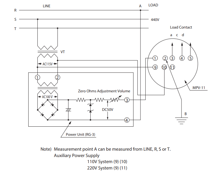
Resistance value between LINE, R, S or T and earth is measured between A and B.
In the diagram on the left, the measurement is taken from phases S and T, but any phase can be used.
The diagram on the left shows an example connection between MPV and 11, but the same result will be obtained between MPC and 12 (vertical terminal array).
The zero ohms adjustment volume is a backup device embedded in the center of the power unit. Insulate auxiliary power supply terminals (9) and (10) before checking the zero
ohms adjustment.
(To stop the output signal of the relay circuit.)
Specified Items when Ordering
Model Name MPV-11 or MPC-12
Scale 0-5 MΩ (Center point 0.2 MΩ)
Auxiliary Power Supply AC, 110V, etc.
Attached Panel Fe or NFe (Specify MPC-12 model only)
Mounting Posture , etc.
Cover Coating Color N-1.5 (black) or 7.5 BG 4/1.5 (blue-green)
Other Non-standard specifications
Related Products
-
Toyo Keiki CF Series AC Voltmeter Rectifier Type
-
Toyo Keiki DVF-11M DC Voltmeter Moving-coil Type
-
TOYO KEIKI GP and HP Series 2output Isolator
-
TOYO KEIKI KGP Series Potentiometer Transducer
-
TOYO KEIKI GP and HP Series Signal Converter
-
Toyo Keiki EVF-11M-RVF-11M Wattmeter and Varmeter Electronic Device Type Time Sharing Multiplication Method


