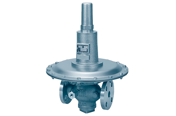
- The RMD31L type back pressure valve is designed for even lower pressure applications.
- It adopts an outlet pressure balance method, so the primary side pressure is hardly affected by fluctuations in outlet side pressure. Additionally, the balance section uses diaphragms or bellows, eliminating friction and leakage.
- The valve body uses synthetic rubber, ensuring excellent sealing performance when the valve is closed.
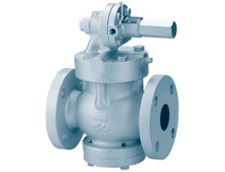
- For nominal diameters of 65 or larger, please use the BRL type back pressure valve.
Specifications and Materials
| Fluid | Primary Side Set Pressure Range (kPa) | Temperature (°C) | Main Component Materials | Pipe Connection | ||||
| Valve Body | Diaphragm Chamber Body | Spring Cover | Valve Seat | Valve Element / Diaphragm | ||||
| Air and Other Non-Corrosive Gases | 0.5–1.4 | 0–80 | Cast Iron | Brass | Cast Iron | Stainless Steel | Synthetic Rubber | Flange JIS 10K Full-Face |
| 1.2–3.3 | ||||||||
| 3.0–8.0 | ||||||||
| 7.0–20 | ||||||||
Note:
- The valve body can also be made of cast steel or stainless steel casting.
- ASME Class 150 is available for nominal diameters 20, 25, 40, and 50.
- The standard synthetic rubber for the valve element and diaphragm is NBR, but FKM (fluoro rubber) and Kalrez® are also available.
- The valve seat can be made without rubber and without bronze if required.
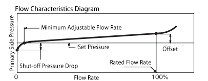
Performance
| Parameter | Value / Description |
|---|---|
| Minimum Set Differential Pressure | 0.5 kPa |
| Offset | 15% or less of the set pressure |
| Shut-off Pressure Drop (¹) | 0.2–1.5 kPa or less |
| Minimum Adjustable Flow Rate (¹) | 0.2–2 m³/h (Standard Condition) |
| Valve Seat Leakage | 0.01% or less of the rated flow rate |
Note (¹): The greater the difference between the set pressure and the outlet pressure, the larger the valve size becomes.
Cv Value
| Nominal Diameter | 15 | 20 | 25 | 32 | 40 | 50 |
|---|---|---|---|---|---|---|
| Cv (Flow Coefficient) | 1.8 | 2.6 | 3.9 | 6.3 | 8.3 | 13 |
Nominal Diameter Selection
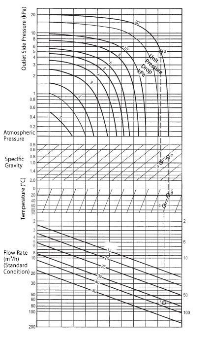
Please select the appropriate nominal diameter using the nominal diameter selection chart.
- If the set pressure and outlet pressure fluctuate within a certain range, select the nominal diameter based on the smallest pressure difference between them.
- The determined nominal diameter does not always match the pipe diameter. The pipe diameter is separately determined by considering allowable pressure loss, piping equipment costs, and other factors.
Translation
Example of Use
- Set Pressure: 20 kPa
- Outlet Pressure: 5.0 kPa
- Temperature: 60°C
- Specific Gravity: 0.8 (compared to air)
- Flow Rate: 70 m³/h (Standard Condition)
Selection Process:
- Pressure Adjustment:
- Find the intersection of outlet pressure (5.0 kPa) and set pressure (20 kPa) → mark point a, then move downward.
- Specific Gravity Adjustment:
- The reference specific gravity is 1.0 (air).
- If the fluid’s specific gravity is 1.0, continue straight down.
- Since the example uses 0.8, move upward along the 0.8 correction line → find intersection b, then move downward.
- Temperature Adjustment:
- The reference temperature is 20°C (standard).
- If the fluid temperature is 20°C, continue straight down.
- Since the example uses 60°C, move downward along the 60°C correction line → find intersection c, then move downward.
- Flow Rate Adjustment:
- From point c, move downward and find the intersection with 70 m³/h flow rate → mark point f.
- Point f falls between nominal diameters 32 and 40.
- Since selecting a larger size is recommended, the nominal diameter 40 is the most suitable selection.
Structure and Dimensions
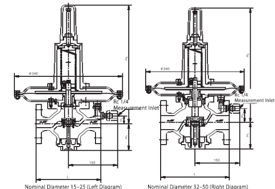
Dimensions and weight
| Nominal Diameter (mm) | L (Length) | H₁ | H₂ | H₃ | Weight (kg) | ||
|---|---|---|---|---|---|---|---|
| Valve Body: Cast Iron | Valve Body: Cast Steel / Stainless Steel Casting | Valve Body: Cast Iron | Valve Body: Cast Steel / Stainless Steel Casting | ||||
| 15 | 180 | 180 | 81 | 368 | 25 | 18.5 | 20 |
| 20 | 185 | 185 | 81 | 368 | 25 | 18.5 | 20 |
| 25 | 196 | 196 | 84 | 372 | 30 | 20 | 21 |
| 32 | 220 | 230 | 92 | 395 | 53 | 23 | 25 |
| 40 | 220 | 230 | 92 | 395 | 53 | 24 | 25 |
| 50 | 230 | 230 | 92 | 395 | 53 | 25 | 27 |
Note: For JP and ASME standards, the external dimensions may differ slightly.
Disassembly & Maintenance Space Requirements
| Nominal Diameter | 15–50 |
|---|---|
| Upward Space from Pipe Center (mm) | 600 |
| Downward Space from Pipe Center (mm) | 320 |
Piping Example
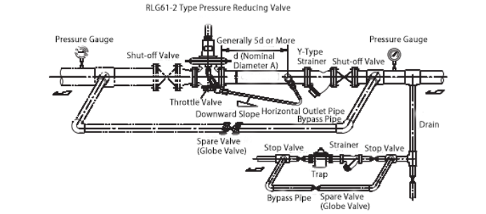
Install the back pressure valve according to the piping example diagram. Most of the operation failures of back pressure valves are due to dirt and debris inside the piping. Before installing the back pressure valve, ensure that the inside of the pipe is thoroughly cleaned.
When installing the back pressure valve and a shut-off valve, make sure that the arrow direction on the body matches the flow direction. Install it in an upright position, and ensure that there is no stress applied to the piping connection.
To prevent external leakage, ensure proper sealing of the connections. Additionally, install a drain at the lowest point of the diaphragm chamber and the horizontal outlet pipe. If condensation drainage is not occurring, inspect and take appropriate measures.
The primary side piping should generally be sized so that the internal flow velocity is 5–15 m/s to ensure proper operation. (Lower flow velocity can increase pressure loss and slow response.)
The throttling valve should normally be fully open. If the back pressure valve operates unstably, adjust the throttling valve gradually. However, do not close it completely, as this may prevent the back pressure valve from functioning properly.
If the fluid is air and the outlet is open to the atmosphere, the double-dashed line section in the diagram is not required.