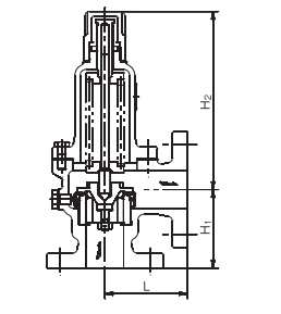
Structure and Dimensions
RPF12 Type・RPF13 Type Saturated Steam Discharge Capacity (According to Pressure Vessel Structure Regulations)
| Nominal Diameter | 15-20 | 25 | 32 | 40 | 50 | 65 | 80 | ||
| Seat Bore Diameter D (mm) | 21 | 26 | 33 | 41 | 51 | 66 | 81 | ||
| Lift l (mm) | 0.6 | 0.7 | 0.9 | 1.1 | 1.3 | 1.7 | 2.1 | ||
| Blowout Area A (mm²)/Set Pressure (MPa·G) | Coefficient C | Set Pressure (MPa·G) | 39.5 | 57.1 | 93.3 | 141.6 | 208.2 | 352.4 | 534.3 |
| 0.1 | 1.000 | 40 | 58 | 95 | 144 | 212 | 359 | 544 | |
| 0.2 | 1.000 | 58 | 84 | 138 | 209 | 308 | 522 | 791 | |
| 0.3 | 1.000 | 78 | 113 | 185 | 282 | 414 | 701 | 1064 | |
| 0.4 | 1.003 | 99 | 143 | 234 | 355 | 522 | 884 | 1340 | |
| 0.5 | 0.999 | 118 | 171 | 280 | 425 | 626 | 1059 | 1606 | |
| 0.6 | 0.995 | 138 | 199 | 326 | 495 | 729 | 1234 | 1871 | |
| 0.7 | 0.991 | 157 | 228 | 372 | 565 | 831 | 1407 | 2133 | |
| 0.8 | 0.987 | 176 | 255 | 417 | 634 | 932 | 1578 | 2393 | |
| 0.9 | 0.985 | 196 | 283 | 463 | 704 | 1035 | 1752 | 2656 | |
| 1.0 | 0.983 | 215 | 311 | 509 | 773 | 1137 | 1925 | 2919 | |
| 1.1 | 0.980 | 234 | 339 | 554 | 841 | 1237 | 2095 | 3177 | |
| 1.2 | 0.978 | 254 | 367 | 600 | 910 | 1339 | 2266 | 3436 | |
| 1.3 | 0.976 | 273 | 394 | 645 | 979 | 1439 | 2437 | 3695 | |
| 1.4 | 0.975 | 292 | 422 | 690 | 1048 | 1541 | 2609 | 3957 | |
| 1.5 | 0.974 | 311 | 450 | 736 | 1117 | 1643 | 2782 | 4218 | |
| 1.6 | 0.973 | 331 | 478 | 782 | 1186 | 1745 | 2953 | 4478 | |
| 1.7 | 0.972 | 350 | 506 | 827 | 1255 | 1846 | 3125 | 4738 | |
| 1.8 | 0.971 | 369 | 534 | 872 | 1324 | 1947 | 3296 | 4998 | |
| 1.9 | 0.970 | 388 | 561 | 917 | 1393 | 2048 | 3467 | 5257 | |
| 2.0 | 0.970 | 408 | 590 | 964 | 1463 | 2151 | 3641 | 5521 | |
RPF12 Type・RPF13 Type・RPS16 Type・RPS17 Type Air Discharge Capacity (According to Pressure Vessel Structure Regulations, at 20°C)
| Nominal Diameter | 15-20 | 25 | 32 | 40 | 50 | 65 | 80 |
| Seat Bore Diameter D (mm) | 21 | 26 | 33 | 41 | 51 | 66 | 81 |
| Lift l (mm) | 0.6 | 0.7 | 0.9 | 1.1 | 1.3 | 1.7 | 2.1 |
| Blowout Area A (mm²)/Set Pressure (MPa·G) | 39.5 | 57.1 | 93.3 | 141.6 | 208.2 | 352.4 | 534.3 |
| 0.1 | 65 | 94 | 153 | 233 | 343 | 581 | 881 |
| 0.2 | 94 | 137 | 223 | 339 | 499 | 845 | 1282 |
| 0.3 | 127 | 184 | 300 | 456 | 671 | 1136 | 1723 |
| 0.4 | 159 | 231 | 377 | 573 | 843 | 1427 | 2163 |
| 0.5 | 192 | 278 | 454 | 690 | 1014 | 1717 | 2604 |
| 0.6 | 225 | 325 | 531 | 807 | 1186 | 2008 | 3045 |
| 0.7 | 257 | 372 | 608 | 923 | 1358 | 2299 | 3486 |
| 0.8 | 290 | 419 | 685 | 1040 | 1530 | 2590 | 3926 |
| 0.9 | 322 | 466 | 762 | 1157 | 1701 | 2880 | 4367 |
| 1.0 | 355 | 513 | 839 | 1274 | 1873 | 3171 | 4808 |
| 1.1 | 388 | 560 | 916 | 1391 | 2045 | 3462 | 5249 |
| 1.2 | 420 | 608 | 993 | 1507 | 2217 | 3752 | 5690 |
| 1.3 | 453 | 655 | 1070 | 1624 | 2388 | 4043 | 6130 |
| 1.4 | 485 | 702 | 1147 | 1741 | 2560 | 4334 | 6571 |
| 1.5 | 518 | 749 | 1224 | 1858 | 2732 | 4625 | 7012 |
| 1.6 | 550 | 796 | 1301 | 1975 | 2904 | 4915 | 7453 |
| 1.7 | 583 | 843 | 1378 | 2092 | 3076 | 5206 | 7893 |
| 1.8 | 616 | 890 | 1455 | 2208 | 3247 | 5497 | 8334 |
| 1.9 | 648 | 937 | 1532 | 2325 | 3419 | 5787 | 8775 |
| 2.0 | 681 | 984 | 1609 | 2442 | 3591 | 6078 | 9216 |
RPF12 Type・RPF13 Type・RPS16 Type・RPS17 Type Air Discharge Capacity (According to High-Pressure Gas Safety Act, at 20°C)
| Nominal Diameter | 15-20 | 25 | 32 | 40 | 50 | 65 | 80 |
| Seat Bore Diameter D (mm) | 21 | 26 | 33 | 41 | 51 | 66 | 81 |
| Lift l (mm) | 0.6 | 0.7 | 0.9 | 1.1 | 1.3 | 1.7 | 2.1 |
| Set Pressure (MPa·G)/Blowout Area A (mm²) | 0.395 | 0.571 | 0.933 | 1.416 | 2.082 | 3.524 | 5.343 |
| 0.1 | 61 | 89 | 145 | 221 | 324 | 550 | 833 |
| 0.2 | 93 | 135 | 221 | 336 | 495 | 838 | 1270 |
| 0.3 | 126 | 182 | 298 | 452 | 665 | 1126 | 1707 |
| 0.4 | 158 | 229 | 374 | 568 | 835 | 1414 | 2144 |
| 0.5 | 190 | 275 | 450 | 684 | 1005 | 1702 | 2581 |
| 0.6 | 223 | 322 | 527 | 799 | 1176 | 1990 | 3018 |
| 0.7 | 255 | 369 | 603 | 915 | 1346 | 2278 | 3454 |
| 0.8 | 287 | 415 | 679 | 1031 | 1516 | 2566 | 3891 |
| 0.9 | 320 | 462 | 755 | 1147 | 1686 | 2854 | 4328 |
| 1.0 | 352 | 509 | 832 | 1262 | 1856 | 3143 | 4765 |
| 1.1 | 384 | 555 | 908 | 1378 | 2027 | 3431 | 5202 |
| 1.2 | 416 | 602 | 984 | 1494 | 2197 | 3719 | 5639 |
| 1.3 | 449 | 649 | 1060 | 1610 | 2367 | 4007 | 6075 |
| 1.4 | 481 | 696 | 1137 | 1726 | 2537 | 4295 | 6512 |
| 1.5 | 513 | 742 | 1213 | 1841 | 2708 | 4583 | 6949 |
| 1.6 | 546 | 789 | 1289 | 1957 | 2878 | 4871 | 7386 |
| 1.7 | 578 | 836 | 1366 | 2073 | 3048 | 5159 | 7823 |
| 1.8 | 610 | 882 | 1442 | 2189 | 3218 | 5447 | 8260 |
| 1.9 | 642 | 929 | 1518 | 2304 | 3388 | 5736 | 8696 |
| 2.0 | 675 | 976 | 1594 | 2420 | 3559 | 6024 | 9133 |
RPF12 Type・RPF13 Type Water Discharge Capacity (According to General Discharge Capacity Calculation Formula)
| Nominal Diameter | 15-20 | 25 | 32 | 40 | 50 | 65 | 80 |
| Seat Bore Diameter D (mm) | 21 | 26 | 33 | 41 | 51 | 66 | 81 |
| Lift l (mm) | 0.6 | 0.7 | 0.9 | 1.1 | 1.3 | 1.7 | 2.1 |
| Set Pressure (MPa·G)/Blowout Area A (mm²) | 39.5 | 57.1 | 93.3 | 141.6 | 208.2 | 352.4 | 534.3 |
| 0.1 | 1349 | 1950 | 3186 | 4836 | 7110 | 12035 | 18248 |
| 0.2 | 1907 | 2757 | 4506 | 6839 | 10056 | 17020 | 25806 |
| 0.3 | 2336 | 3377 | 5519 | 8376 | 12316 | 20846 | 31606 |
| 0.4 | 2698 | 3900 | 6372 | 9672 | 14221 | 24071 | 36496 |
| 0.5 | 3016 | 4360 | 7125 | 10813 | 15900 | 26912 | 40803 |
| 0.6 | 3304 | 4776 | 7805 | 11845 | 17417 | 29481 | 44698 |
| 0.7 | 3569 | 5159 | 8430 | 12795 | 18813 | 31843 | 48279 |
| 0.8 | 3815 | 5515 | 9012 | 13678 | 20112 | 34041 | 51613 |
| 0.9 | 4047 | 5850 | 9559 | 14508 | 21332 | 36106 | 54744 |
| 1.0 | 4266 | 6166 | 10076 | 15293 | 22486 | 38059 | 57705 |
| 1.1 | 4474 | 6467 | 10568 | 16039 | 23583 | 39917 | 60522 |
| 1.2 | 4673 | 6755 | 11038 | 16752 | 24632 | 41692 | 63213 |
| 1.3 | 4864 | 7031 | 11489 | 17436 | 25638 | 43395 | 65794 |
| 1.4 | 5047 | 7296 | 11922 | 18095 | 26605 | 45033 | 68278 |
| 1.5 | 5224 | 7552 | 12341 | 18730 | 27539 | 46613 | 70674 |
| 1.6 | 5396 | 7800 | 12745 | 19344 | 28442 | 48142 | 72992 |
| 1.7 | 5562 | 8040 | 13138 | 19939 | 29318 | 49624 | 75238 |
| 1.8 | 5723 | 8273 | 13519 | 20517 | 30168 | 51062 | 77420 |
| 1.9 | 5880 | 8500 | 13889 | 21080 | 30994 | 52461 | 79541 |
| 2.0 | 6033 | 8721 | 14250 | 21627 | 31800 | 53824 | 81607 |
Notes:
- The discharge capacity calculation formula is based on the vent well calculation formula in the High-Pressure Gas Safety Act.
- This table applies to cases where the back pressure of the discharge outlet is atmospheric pressure and the overpressure is 25%.
- If G ≠ 1, multiply the values in the table by the G value to obtain the required discharge capacity.