Fushiman Co.
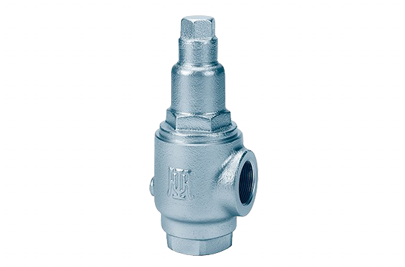
Fushiman RPC14 relief valve
Manufacturer: Fushiman Co.,LTD.
Model: RPC14
| Model | Nominal diameter | fluid | Set pressure | Maximum operating temperature | Body Material | Connection |
|---|---|---|---|---|---|---|
| RPC14 | 15〜40 | Liquid | 0.04 to 1.6 MPa | 200℃ | FC | Fflange |
Features
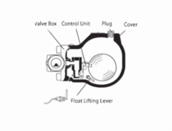
- A dashpot is installed in the valve disc and valve seat, making it less likely to cause chattering. Additionally, it prevents damage to the seat surface, eliminates noise issues, and protects the equipment.
- With a fully sealed structure, it can also be used in locations where there is some back pressure on the discharge side.
- It can also be used as a simple back pressure valve.
Specifications and Materials
| Shape | Sealed Type without Lever | |
| Fluid | Water, Oil, Non-Corrosive Liquid | |
| Pressure | Set 0.04–1.6 MPa (Back Pressure: 1.0 MPa or Less) | |
| Operating Temperature | 0–200°C | |
| Maximum Usable Viscosity | 2000 mm²/s (At Operating Temperature) | |
| Materials | Valve Body | Cast Iron |
| Valve Seat | Stainless Steel | |
| Valve Disc | Stainless Steel | |
| Valve Stem | Stainless Steel | |
| Spring Protection Tube | Cast Iron | |
| Adjustment Spring | Spring Steel, Piano Wire | |
| Cover | Cast Iron | |
| Adjustment Screw | Brass | |
| Applications | Pump Bypass, Back Pressure Valve | |
| Applicable Standards | Pressure Vessel Structural Standards | |
When there is pressure (back pressure) on the discharge side, the blow-off pressure will differ from the valve’s set pressure.
Additionally, if the back pressure changes, the blow-off pressure will also change.
When there is back pressure, the inlet-side pressure will be the set pressure plus the back pressure.
The maximum inlet-side pressure is 1.6 MPa.
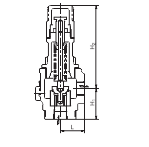
Dimensions and Mass
| Nominal Diameter (Inlet × Outlet) | Face-to-Face Distance | Height (H₂) | Pipe Connection | Mass (kg) | ||
|---|---|---|---|---|---|---|
| L | H₁ | Inlet | Outlet | |||
| 15 × 15 | 38 | 48 | 129 | JIS Rc Threaded | JIS Rc Threaded | 1.5 |
| 20 × 20 | 38 | 48 | 129 | JIS Rc Threaded | JIS Rc Threaded | 2 |
| 25 × 25 | 44 | 56 | 140 | JIS Rc Threaded | JIS Rc Threaded | 3 |
| 32 × 32 | 51 | 70 | 162 | JIS Rc Threaded | JIS Rc Threaded | 4 |
| 40 × 40 | 57 | 75 | 182 | JIS Rc Threaded | JIS Rc Threaded | 5 |
RPC14 Model Water Discharge Volume (Based on General Discharge Volume Calculation Formula)
| Nominal Diameter | 15 | 20 | 25 | 32 | 40 | 50 | 65 | 80 |
| Seat Bore Diameter D (mm) | 20 | 20 | 25 | 32 | 40 | 50 | 65 | 80 |
| Lift l (mm) | 0.28 | 0.5 | 0.63 | 0.8 | 1.0 | 1.25 | 1.63 | 2.0 |
| Set Pressure (MPa·G)/ Blowout Area A (mm²) | 12.4 | 22.2 | 34.9 | 56.8 | 88.8 | 138.8 | 235.3 | 355.3 |
| 0.1 | 423 | 758 | 1191 | 1939 | 3032 | 4740 | 8036 | 12134 |
| 0.2 | 598 | 1072 | 1685 | 2743 | 4289 | 6704 | 11364 | 17160 |
| 0.3 | 733 | 1313 | 2064 | 3360 | 5252 | 8210 | 13919 | 21017 |
| 0.4 | 847 | 1516 | 2383 | 3879 | 6065 | 9480 | 16072 | 24269 |
| 0.5 | 946 | 1695 | 2665 | 4337 | 6781 | 10600 | 17969 | 27133 |
| 0.6 | 1037 | 1857 | 2919 | 4751 | 7428 | 11611 | 19684 | 29723 |
| 0.7 | 1120 | 2006 | 3153 | 5132 | 8024 | 12542 | 21261 | 32105 |
| 0.8 | 1197 | 2144 | 3371 | 5486 | 8578 | 13408 | 22729 | 34321 |
| 0.9 | 1270 | 2274 | 3575 | 5819 | 9098 | 14221 | 24108 | 36403 |
| 1.0 | 1339 | 2397 | 3769 | 6134 | 9590 | 14990 | 25412 | 38373 |
| 1.1 | 1404 | 2514 | 3953 | 6433 | 10058 | 15722 | 26653 | 40246 |
| 1.2 | 1467 | 2626 | 4129 | 6720 | 10505 | 16421 | 27838 | 42035 |
| 1.3 | 1526 | 2733 | 4297 | 6994 | 10934 | 17092 | 28975 | 43752 |
| 1.4 | 1584 | 2836 | 4459 | 7258 | 11347 | 17737 | 30068 | 45403 |
| 1.5 | 1640 | 2936 | 4616 | 7513 | 11746 | 18359 | 31124 | 46997 |
| 1.6 | 1694 | 3032 | 4767 | 7759 | 12131 | 18961 | 32145 | 48538 |
| 1.7 | 1746 | 3126 | 4914 | 7998 | 12504 | 19545 | 33134 | 50032 |
| 1.8 | 1796 | 3216 | 5057 | 8230 | 12867 | 20112 | 34094 | 51482 |
| 1.9 | 1845 | 3304 | 5195 | 8455 | 13219 | 20663 | 35029 | 52893 |
| 2.0 | 1893 | 3390 | 5330 | 8675 | 13563 | 21200 | 35939 | 54267 |
- The discharge volume calculation formula is based on the calculation formula for relief valves in the High-Pressure Gas Safety Act.
- This table applies when the valve outlet pressure is atmospheric pressure and the overpressure is 25%.
- If G ≠ 1, multiply the values in the table by the corresponding G value to obtain the required discharge volume.
R101-1BHA Model Water Discharge Volume (Based on General Discharge Volume Calculation Formula)
| Nominal Diameter | 15-20 | 25 | 32 | 40 |
| Seat Bore Diameter D (mm) | 20 | 25 | 32 | 40 |
| Lift l (mm) | 0.7 | 0.8 | 1.0 | 1.3 |
| Set Pressure (MPa·G)/ Blowout Area A (mm²) | 43.9 | 62.8 | 100.5 | 163.3 |
| 0.1 | 1499 | 2144 | 3432 | 5645 |
| 0.2 | 2120 | 3033 | 4854 | 7983 |
| 0.3 | 2596 | 3714 | 5945 | 9778 |
| 0.4 | 2998 | 4289 | 6864 | 11291 |
| 0.5 | 3352 | 4795 | 7675 | 12623 |
| 0.6 | 3672 | 5253 | 8407 | 13828 |
| 0.7 | 3966 | 5674 | 9081 | 14936 |
| 0.8 | 4240 | 6066 | 9708 | 15967 |
| 0.9 | 4497 | 6434 | 10297 | 16936 |
| 1.0 | 4741 | 6782 | 10854 | 17852 |
| 1.1 | 4972 | 7113 | 11383 | 18724 |
| 1.2 | 5193 | 7429 | 11890 | 19556 |
| 1.3 | 5405 | 7733 | 12375 | 20355 |
| 1.4 | 5609 | 8025 | 12842 | 21123 |
| 1.5 | 5806 | 8306 | 13293 | 21865 |
| 1.6 | 5997 | 8579 | 13729 | 22582 |
- The discharge volume calculation formula is based on the calculation formula for relief valves in the High-Pressure Gas Safety Act.
- This table applies when the valve outlet pressure is atmospheric pressure and the overpressure is 25%.
- If G ≠ 1, multiply the values in the table by the corresponding G value to obtain the required discharge volume.
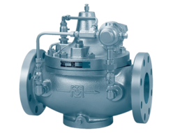
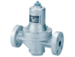
Related Products

REQUEST QUOTATION

PAYMENT

LINK


