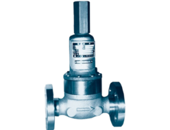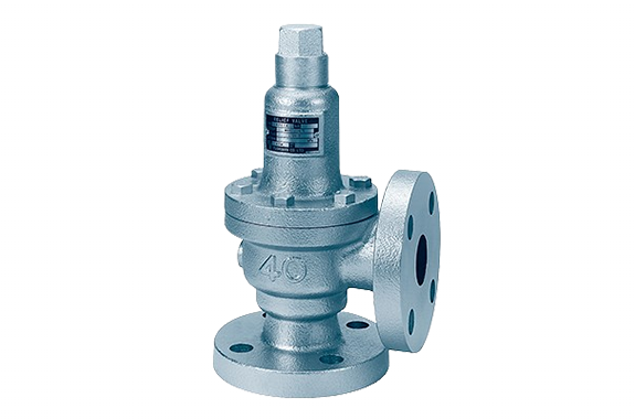
RPC14 type ・ Cast iron ・ 16K ・ Same as the screw-in shape.
| Shape | Leverless Sealed Type | |
| Fluid | Water, Oil, Non-Corrosive Liquids | |
| Pressure | Set Pressure: 0.04–16 MPa (Back Pressure: 1.0 MPa or less) | |
| Operating Temperature | 0–200°C | |
| Maximum Usable Viscosity | 2000 mm²/s (At Operating Temperature) | |
| Material | Valve Box | Cast Iron (15A–40A JIS 16K is Ductile Cast Iron) |
| Valve Seat | Stainless Steel | |
| Valve Body | Stainless Steel | |
| Valve Stem | Stainless Steel | |
| Spring Protection Tube | Cast Iron | |
| Adjustment Spring | Spring Steel, Piano Wire | |
| Lid | Cast Iron | |
| Adjustment Screw | Brass | |
| Application | Pump Bypass, Back Pressure Valve | |
| Applicable Standards | Pressure Vessel Structural Standards | |
Note (1): We will also consider cases where the viscosity exceeds 2000 mm²/s.
If there is pressure (back pressure) on the outlet side, the blow-off pressure will differ from the set pressure of the valve.
Additionally, if the back pressure changes, the blow-off pressure will also change.
When there is back pressure, the inlet pressure will be the set pressure plus the back pressure. The maximum inlet pressure is the same as the nominal flange pressure.
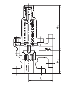
Dimensions and Mass
| Nominal Diameter (Inlet × Outlet) | Face-to-Face Dimensions | Height (H₂) | Pipe Connection | Weight | ||
| L | Hi | Inlet | Outlet | |||
| 15X 15 | 73 | 68 | 136 | JIS10K 全面座 | JIS10K 全面座 | 3.8 |
| 20 x 20 | 75 | 70 | 136 | 4.2 | ||
| 25 x 25 | 85 | 85 | 148 | 6.5 | ||
| 32 x 32 | 95 | 90 | 172 | 9.2 | ||
| 40 x 40 | 100 | 95 | 191 | 10.8 | ||
| 50 x 50 | 110 | 105 | 238 | 15.6 | ||
| 65 x 65 | 130 | 120 | 286 | 25.7 | ||
| 80 x 80 | 140 | 135 | 343 | 33.2 | ||
| 15X 20 | 75 | 83 | 143 | JIS 16K 全面座 | JIS10K 全面座 | 4.7 |
| 20 x 25 | 75 | 85 | 143 | 5.4 | ||
| 25 x 32 | 90 | 90 | 158 | 7.5 | ||
| 32 x 40 | 95 | 95 | 183 | 10 | ||
| 40 x 50 | 100 | 105 | 206 | 13 | ||
| 50 x 65 | 115 | 115 | 250 | 17.2 | ||
| 65 x 80 | 130 | 130 | 303 | 26.5 | ||
| 80X100 | 145 | 145 | 358 | 38 | ||
RPC14 Model Water Discharge Volume (Based on General Discharge Volume Calculation Formula)
| Nominal Diameter | 15 | 20 | 25 | 32 | 40 | 50 | 65 | 80 |
| Seat Bore Diameter D (mm) | 20 | 20 | 25 | 32 | 40 | 50 | 65 | 80 |
| Lift l (mm) | 0.28 | 0.5 | 0.63 | 0.8 | 1.0 | 1.25 | 1.63 | 2.0 |
| Set Pressure (MPa·G)/ Blowout Area A (mm²) | 12.4 | 22.2 | 34.9 | 56.8 | 88.8 | 138.8 | 235.3 | 355.3 |
| 0.1 | 423 | 758 | 1191 | 1939 | 3032 | 4740 | 8036 | 12134 |
| 0.2 | 598 | 1072 | 1685 | 2743 | 4289 | 6704 | 11364 | 17160 |
| 0.3 | 733 | 1313 | 2064 | 3360 | 5252 | 8210 | 13919 | 21017 |
| 0.4 | 847 | 1516 | 2383 | 3879 | 6065 | 9480 | 16072 | 24269 |
| 0.5 | 946 | 1695 | 2665 | 4337 | 6781 | 10600 | 17969 | 27133 |
| 0.6 | 1037 | 1857 | 2919 | 4751 | 7428 | 11611 | 19684 | 29723 |
| 0.7 | 1120 | 2006 | 3153 | 5132 | 8024 | 12542 | 21261 | 32105 |
| 0.8 | 1197 | 2144 | 3371 | 5486 | 8578 | 13408 | 22729 | 34321 |
| 0.9 | 1270 | 2274 | 3575 | 5819 | 9098 | 14221 | 24108 | 36403 |
| 1.0 | 1339 | 2397 | 3769 | 6134 | 9590 | 14990 | 25412 | 38373 |
| 1.1 | 1404 | 2514 | 3953 | 6433 | 10058 | 15722 | 26653 | 40246 |
| 1.2 | 1467 | 2626 | 4129 | 6720 | 10505 | 16421 | 27838 | 42035 |
| 1.3 | 1526 | 2733 | 4297 | 6994 | 10934 | 17092 | 28975 | 43752 |
| 1.4 | 1584 | 2836 | 4459 | 7258 | 11347 | 17737 | 30068 | 45403 |
| 1.5 | 1640 | 2936 | 4616 | 7513 | 11746 | 18359 | 31124 | 46997 |
| 1.6 | 1694 | 3032 | 4767 | 7759 | 12131 | 18961 | 32145 | 48538 |
| 1.7 | 1746 | 3126 | 4914 | 7998 | 12504 | 19545 | 33134 | 50032 |
| 1.8 | 1796 | 3216 | 5057 | 8230 | 12867 | 20112 | 34094 | 51482 |
| 1.9 | 1845 | 3304 | 5195 | 8455 | 13219 | 20663 | 35029 | 52893 |
| 2.0 | 1893 | 3390 | 5330 | 8675 | 13563 | 21200 | 35939 | 54267 |
- The discharge volume calculation formula is based on the calculation formula for relief valves in the High-Pressure Gas Safety Act.
- This table applies when the valve outlet pressure is atmospheric pressure and the overpressure is 25%.
- If G ≠ 1, multiply the values in the table by the corresponding G value to obtain the required discharge volume.
R101-1BHA Model Water Discharge Volume (Based on General Discharge Volume Calculation Formula)
| Nominal Diameter | 15-20 | 25 | 32 | 40 |
| Seat Bore Diameter D (mm) | 20 | 25 | 32 | 40 |
| Lift l (mm) | 0.7 | 0.8 | 1.0 | 1.3 |
| Set Pressure (MPa·G)/ Blowout Area A (mm²) | 43.9 | 62.8 | 100.5 | 163.3 |
| 0.1 | 1499 | 2144 | 3432 | 5645 |
| 0.2 | 2120 | 3033 | 4854 | 7983 |
| 0.3 | 2596 | 3714 | 5945 | 9778 |
| 0.4 | 2998 | 4289 | 6864 | 11291 |
| 0.5 | 3352 | 4795 | 7675 | 12623 |
| 0.6 | 3672 | 5253 | 8407 | 13828 |
| 0.7 | 3966 | 5674 | 9081 | 14936 |
| 0.8 | 4240 | 6066 | 9708 | 15967 |
| 0.9 | 4497 | 6434 | 10297 | 16936 |
| 1.0 | 4741 | 6782 | 10854 | 17852 |
| 1.1 | 4972 | 7113 | 11383 | 18724 |
| 1.2 | 5193 | 7429 | 11890 | 19556 |
| 1.3 | 5405 | 7733 | 12375 | 20355 |
| 1.4 | 5609 | 8025 | 12842 | 21123 |
| 1.5 | 5806 | 8306 | 13293 | 21865 |
| 1.6 | 5997 | 8579 | 13729 | 22582 |
- The discharge volume calculation formula is based on the calculation formula for relief valves in the High-Pressure Gas Safety Act.
- This table applies when the valve outlet pressure is atmospheric pressure and the overpressure is 25%.
- If G ≠ 1, multiply the values in the table by the corresponding G value to obtain the required discharge volume.