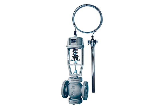
Note (3): Valve bodies can also be manufactured from cast steel or cast stainless steel (for heating: Model 888A, for cooling: Model 888R).
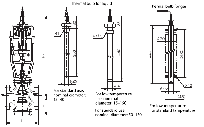
Note (4): For thermal bulbs used with liquids, versions with protective sleeves can also be manufactured.
Remark 1: Thermal bulb connection parts can also be manufactured in flange type.
2: If the thermal bulb is pressurized in gas applications, please specify accordingly.
Dimensions, Weight, and Cv Value
| Category | 15A | 20A | 25A | 32A | 40A | 50A | 65A | 80A | 100A | 125A | 150A |
|---|---|---|---|---|---|---|---|---|---|---|---|
| L (mm) | 140 | 145 | 160 | 180 | 195 | 200 | 220 | 240 | 280 | 370 | 450 |
| H₁ (mm) | 73 | 73 | 78 | 86 | 98 | 113 | 118 | 138 | 151 | 178 | 208 |
| H₂ (mm) | 465 | 465 | 475 | 480 | 490 | 515 | 521 | 568 | 581 | 607 | 637 |
| Head Outer Diameter (mm) | 160 | 160 | 160 | 160 | 160 | 160 | 160 | 180 | 180 | 180 | 180 |
| Weight (kg) | 12 | 13 | 15 | 19 | 21 | 30 | 32 | 40 | 57 | 98 | 130 |
| Cv Value | 4 | 4 | 7 | 10 | 13 | 20 | 22 | 32 | 47 | 100 | 110 |
Standard Set Temperature Ranges
| Type | Set Temperature Range | Temperature Resistance |
|---|---|---|
| Low Temperature | 15°C or higher – 30°C or lower | 45°C |
| 20°C or higher – 40°C or lower | 50°C | |
| 35°C or higher – 55°C or lower | 70°C | |
| Standard Temperature | 40°C or higher – 60°C or lower | 70°C |
| 50°C or higher – 70°C or lower | 80°C | |
| 60°C or higher – 80°C or lower | 90°C | |
| 70°C or higher – 90°C or lower | 100°C | |
| 80°C or higher – 100°C or lower | 110°C | |
| 90°C or higher – 110°C or lower | 120°C | |
| 100°C or higher – 120°C or lower | 130°C |
When the set temperature range is for low temperature use, the structure of the temperature control valve differs slightly from the illustration on the previous page.
Valve Opening/Closing Temperature Differential
| Category | For Liquid | For Gas | ||
|---|---|---|---|---|
| Standard Temp | Low Temp | Standard Temp | Low Temp | |
| CT 3m | 4.5°C or less | 5°C or less | 7.5°C or less | 8°C or less |
Nominal Diameter Selection (Example)
○Fluid: Saturated Steam
○Primary Side Pressure: 0.53 MPa
○Flow Rate: 300 kg/h
◎How to determine the appropriate valve nominal diameter when the allowable pressure drop is 0.1 MPa:
① Draw a horizontal line to the right from the saturation point at secondary side steam pressure: 0.43 MPa (0.53 − 0.1 MPa).
② Draw a vertical line upward from the point where it intersects with the 300 kg/h steam flow line.
③ Find the intersection with the 0.1 MPa allowable pressure drop line.
↳ This falls between nominal diameters 20 and 25. Choose the larger one, so “nominal diameter 25” is considered appropriate.
Nominal Diameter Selection Chart