Fushiman Co.
Fushiman SFH type/SMFH type temperature control valve
Manufacturer: Fushiman Co.,LTD.
Model: SFH / SMFH
| Model | Nominal diameter | Pressure | Temperature setting | Body Material | Connection |
|---|---|---|---|---|---|
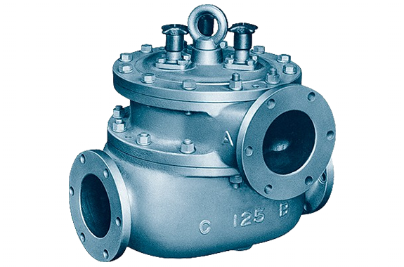
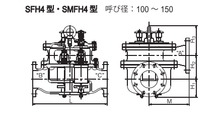
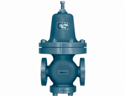
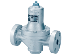
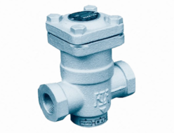
| The photo shows the SFH4 and SMFH4. | 25–250 | Max. 1.0MPa | 25 to 87°C | FC | Flanges |
Application
This temperature control valve is an automatic three-way valve using a wax-type thermostat (element). It is widely used for temperature regulation of cooling water, lubricating oil, and hydraulic oil in engines, compressors, gear reducers, and industrial machinery, as well as in HVAC systems, hot water supply, and refrigeration equipment.
Specification
| Item | Description |
|---|---|
| Working Fluid | Clean water, hot water, lubricating oil, fuel oil |
| Max Operating Pressure | 1.0 MPa |
| Allowable Differential Pressure | 0.15 MPa (between A–C or B–C) |
| Pipe Connection | JIS 10K Flange |
| Material – Body | Cast iron, cast steel, or cast stainless steel (See page 158 for dimensions and weight) |
| Material – Main Parts | Bronze, stainless steel |
| Assembly Direction (*) | Normal assembly, reverse assembly |
Note (*1): Models SFH3A and SMFH3A are for normal assembly only.
Types of Control Methods
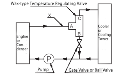
Diverting Type
This method controls the flow rate to the cooler based on the temperature of the fluid entering point A, in order to maintain a constant temperature at point X.
Mixing Type
This method regulates the mixing ratio between the fluid entering point B and the fluid cooled through the cooler, based on the temperature of the fluid at B, to maintain a constant temperature at point Y.
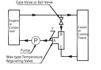
Port Symbols and Names
A: Engine or Condenser
B: Bypass
C: Cooler or Cooling Tower
Note: Please specify the control method when placing an order.
Model Name, Control Method, and Nominal Diameter Relationship
| Diverting Type | Mixing Type | Nominal Diameter (mm) |
|---|---|---|
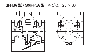
| SFH3A Model | SMFH3A Model | 25–80 |
| SFH4 Model | SMFH4 Model | 100–150 |
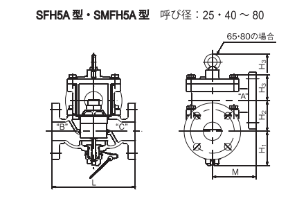
| SFH5A Model | SMFH5A Model | 25・40–80 |
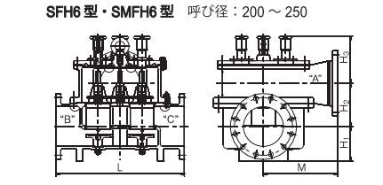
| SFH6 Model | SMFH6 Model | 200・250 |
Model Name Notation
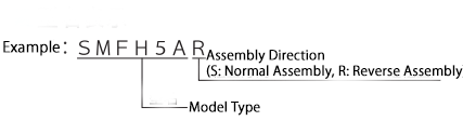
Features
Compact and lightweight, yet the element provides powerful output.
No external power such as electricity, hydraulic, or pneumatic pressure is required—making it economical.
Models S(M)FH4, S(M)FH5A, and S(M)FH6 can be maintained, inspected, and have elements replaced without removing piping.
In emergencies, manual operation can prevent overheating of the fluid.
Can be installed in both horizontal and vertical piping. However, for maintenance and inspection purposes, it is recommended to install upright (as shown on page 158).
Operating characteristics are not affected by ambient temperature.
Fluid leakage from sliding parts is minimal.
Types of Standard Set Temperatures
| Standard Set Temperature (°C) (*) | 25 | 30 | 35 | 40 | 45 | 50 | 55 | 60 | 65 | 70 | 75 | 80 | 85 | 87 |
|---|---|---|---|---|---|---|---|---|---|---|---|---|---|---|
| Operating Temperature Range (°C) | 20/30 | 25/35 | 30/40 | 35/45 | 40/50 | 45/55 | 50/60 | 55/65 | 60/70 | 65/75 | 70/80 | 75/85 | 80/90 | 82/92 |
Note (*): Usable up to set temperature +20°C. Please ensure it does not exceed this limit.
Dimensions, Cv, and Weight Table
SFH3A Model, SMFH3A Model
| Category / Nominal Diameter | 25 | 32 | 40 | 50 | 65 | 80 | |
| H1 | 88 | 93 | 93 | 96 | 103 | 115 | |
| H2 | 117 | 134 | 134 | 134 | 167 | 177 | |
| L | 188 | 228 | 228 | 228 | 298 | 318 | |
| Number of Elements | 1 | 1 | 1 | 1 | 2 | 2 | |
| Weight (kg) | F | 10.5 | 14 | 15 | 18 | 33 | 42.5 |
| S | 10.5 | — | 17 | 19.5 | — | 46.5 | |
| Cv Value | 6.5 | 22 | 31.2 | 45.8 | 114 | 152 | |
SFH5A Model ・ SMFH5A Model
| Category / Nominal Diameter | 25 | 32 | 40 | 50 | 65 | 80 | |
| H1 | 88 | 93 | 93 | 96 | 103 | 115 | |
| H2 | 68 | 84 | 84 | 84 | 146.5 | 157.5 | |
| H3 | 53.3 | 70 | 70 | 70 | 160 | 167.5 | |
| L | 188 | 228 | 228 | 228 | 298 | 318 | |
| M | 94 | 119.5 | 119.5 | 119.5 | 187 | 204 | |
| Number of Elements | 1 | 1 | 1 | 1 | 2 | 2 | |
| Weight (kg) | F | 13 | 19 | 21 | 24 | 43 | 54 |
| S | 14 | — | 23 | 26 | — | 59 | |
| Cv Value | 6.5 | 22 | 31.2 | 45.8 | 114 | 152 | |
SFH4 Model ・ SMFH4 Model
| Category / Nominal Diameter | 100 | 125 | 150 | |
| H1 | 128 | 128 | 128 | |
| H2 | 160 | 170 | 180 | |
| H3 | 162 | 213 | 221 | |
| L | 388 | 532 | 608 | |
| M | 264 | 286 | 344 | |
| Number of Elements | 2 | 3 | 4 | |
| Weight (kg) | F | 83 | 160 | 215 |
| S | 110 | 174 | 237 | |
| Cv Value | 230 | 330 | 433 | |
SFH6 Model ・ SMFH6 Model
| Category / Nominal Diameter | 200 | 250 | |
| H1 | 175 | 215 | |
| H2 | 216 | 246.5 | |
| H3 | 238 | 241 | |
| L | 644 | 728 | |
| M | 372 | 414 | |
| Number of Elements | 4 | 6 | |
| Weight (kg) | F | 245 | 355 |
| S | 270 | — | |
| Cv Value | 768 | 1200 | |
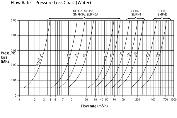
Nominal Diameter Selection
The nominal diameter is usually matched to the counterpart flange. However, when determining it by calculating the pressure loss (sizing ΔP), a flow rate vs. pressure loss chart is used. Normally, the sizing ΔP is selected to be 0.03 MPa or less.
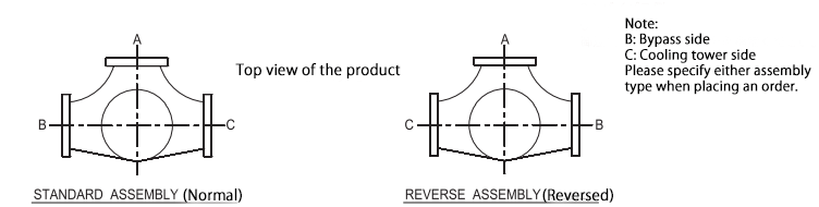
Assembly Orientation (Viewed from Above)
For models S(M)FH5A, S(M)FH4, and S(M)FH6, please specify the orientation of ports B and C relative to port A when placing your order. If no specification is provided, the product will be delivered in the STANDARD (normal assembly) configuration.
Piping Example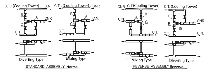
Related Products
REQUEST QUOTATION

PAYMENT

LINK


