Fushiman Co.
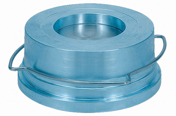
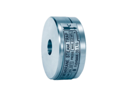
Fushiman RK44 type check valve
Manufacturer: Fushiman Co.,LTD.
Model: RK44
| Model | Nominal diameter | Fluid | Maximum Operating Pressure | Maximum Operating Temperature | Body Material | Connection |
|---|---|---|---|---|---|---|
| RK44 | 15–100 | Steam Gas Liquid | 1.6 MPa | 225°C | Bronze | Wafer |
Wafer type, compact, and lightweight — installation orientation is optional.
Specifications
| Model | RK44-RK41 | |||||||
| Description | The maximum operating pressure and temperature vary depending on the flange standard. | |||||||
| Type of Disc Contact Surface | Metal Seat | Soft Seat | ||||||
| Applicable Fluid | Liquid, gas, and steam | Water, condensate, and steam | Mineral oil | Gas and air | ||||
| Maximum Operating Pressure (MPa) | 1.6 | 1-4 | 1.3 | 1.6 | 1.6 | 1.6 | 1.4 | |
| Maximum Operating Temperature (°C) | 120 | 200 | 225 | 120 | 120 | 120 | 160 | |
| Material | Disc | Nominal diameter 15–100: Stainless steel | EPDM | Fluororubber | ||||
| Nominal diameter 125–200: Cast iron | ||||||||
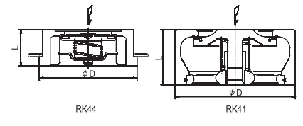
| Body & Seat (Integral) | RK44 type (Nominal diameter 15–100) RK41 type (Nominal diameter 125–200) | Bronze / Cast iron (¹) | ||||||
| Spring | Stainless steel | |||||||
| Pipe Connection: Compatible Flanges | Wafer type: JIS 10K/16K, DIN PN 6/10/16, ASME Class 125 FF (for all nominal diameters), ASME Class 150 RF (for nominal diameter 125–200 only) | |||||||
Note (¹): We also manufacture the RK44S type with a bronze valve body.
| Model | RK44 | RK41 | |||||||||||||
| Nominal Diameter | 15 | 20 | 25 | 32 | 40 | 50 | 65 | 80 | 100 | 125 | 150 | 200 | |||
| Dimensions | L | 16 | 19 | 22 | 28 | 31.5 | 40 | 46 | 50 | 60 | 90 | 106 | 140 | ||
| D | 42 | 49 | 58 | 74 | 84 | 97 | 117 | 132 | 152 | 184 | 209 | 264 | |||
| Opening Pressure | Installation Orientation | Without Spring | ↑ | 0.25 | 0.25 | 0.25 | 0.35 | 0.40 | 0.45 | 0.50 | 0.55 | 0.65 | 1.25 | 1.4 | 1.35 |
| With Spring | ↑ | 1.00 | 1.00 | 1.00 | 1.20 | 1.30 | 1.40 | 1.50 | 1.60 | 1.80 | 3.5 | 3.8 | 3.7 | ||
| → | 0.75 | 0.75 | 0.75 | 0.85 | 0.90 | 0.95 | 1.00 | 1.05 | 1.15 | 2.25 | 2.4 | 2.35 | |||
| ↓ | 0.50 | 0.50 | 0.50 | 0.50 | 0.50 | 0.50 | 0.50 | 0.50 | 0.50 | 1.00 | 1.00 | 1.00 | |||
| Cv Value | 4.3 | 7.9 | 12 | 18 | 27 | 43 | 68 | 90 | 135 | 262 | 354 | 597 | |||
| Weight | 0.1 | 0.2 | 0.25 | 0.5 | 0.7 | 1.1 | 1.4 | 2 | 3.2 | 6.8 | 10 | 20 | |||
Note: The allowable tolerance for opening pressure is ±20%. Do not use for pressure regulation purposes.
Pressure Loss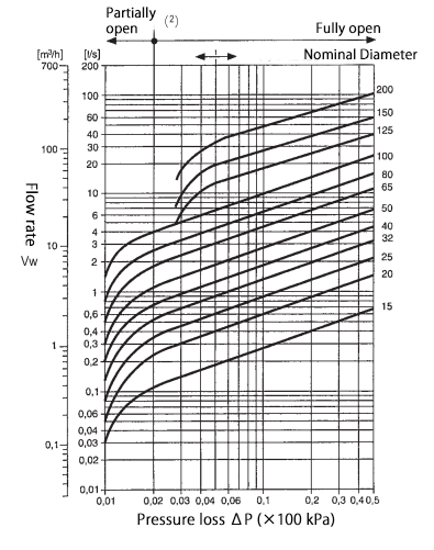
Note (²): Do not use in partial opening (pressure loss ΔP ≤ 2 kPa or 5 kPa), as there is a possibility of chattering.
The graph lines show the case of water at 20°C.
To estimate the pressure loss for other fluids, read the graph value using the equivalent flow rate:
Vw = V × ρ / 1000
Where:
Vw = Equivalent flow rate (ℓ/s or m³/h)
ρ = Fluid density (operating) (kg/m³)
V = Actual flow rate (operating) (ℓ/s or m³/h)The graph assumes horizontal piping unless otherwise stated.
In vertical piping, there may be slight differences before the valve is fully opened, but once fully opened (normal flow state), the same conditions apply as for horizontal piping.
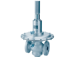
Related Products
REQUEST QUOTATION

PAYMENT

LINK


