Fushiman Co.
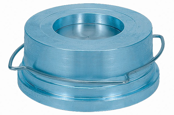
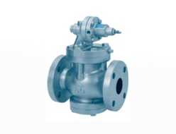
Fushiman RK41 type check valve
Manufacturer: Fushiman Co.,LTD.
Model: RK41
| Model | Nominal diameter | Fluid | Maximum Operating Pressure | Maximum Operating Temperature | Body Material | Connection |
|---|---|---|---|---|---|---|
| RK41 | 15–100 | Steam Gas Liquid | 1.6 MPa | 225°C | Bronze | Wafer |
Wafer type, compact, and lightweight — installation orientation is optional.
Specifications
| Model | RK44-RK41 | |||||||
| Description | The maximum operating pressure and temperature vary depending on the flange standard. | |||||||
| Type of Disc Contact Surface | Metal Seat | Soft Seat | ||||||
| Applicable Fluid | Liquid, gas, and steam | Water, condensate, and steam | Mineral oil | Gas and air | ||||
| Maximum Operating Pressure (MPa) | 1.6 | 1-4 | 1.3 | 1.6 | 1.6 | 1.6 | 1.4 | |
| Maximum Operating Temperature (°C) | 120 | 200 | 225 | 120 | 120 | 120 | 160 | |
| Material | Disc | Nominal diameter 15–100: Stainless steel | EPDM | Fluororubber | ||||
| Nominal diameter 125–200: Cast iron | ||||||||
| Body & Seat (Integral) | RK44 type (Nominal diameter 15–100) RK41 type (Nominal diameter 125–200) | Bronze / Cast iron (¹) | ||||||
| Spring | Stainless steel | |||||||
| Pipe Connection: Compatible Flanges | Wafer type: JIS 10K/16K, DIN PN 6/10/16, ASME Class 125 FF (for all nominal diameters), ASME Class 150 RF (for nominal diameter 125–200 only) | |||||||
Note (¹): We also manufacture the RK44S type with a bronze valve body.
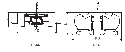
| Model | RK44 | RK41 | |||||||||||||
| Nominal Diameter | 15 | 20 | 25 | 32 | 40 | 50 | 65 | 80 | 100 | 125 | 150 | 200 | |||
| Dimensions | L | 16 | 19 | 22 | 28 | 31.5 | 40 | 46 | 50 | 60 | 90 | 106 | 140 | ||
| D | 42 | 49 | 58 | 74 | 84 | 97 | 117 | 132 | 152 | 184 | 209 | 264 | |||
| Opening Pressure | Installation Orientation | Without Spring | ↑ | 0.25 | 0.25 | 0.25 | 0.35 | 0.40 | 0.45 | 0.50 | 0.55 | 0.65 | 1.25 | 1.4 | 1.35 |
| With Spring | ↑ | 1.00 | 1.00 | 1.00 | 1.20 | 1.30 | 1.40 | 1.50 | 1.60 | 1.80 | 3.5 | 3.8 | 3.7 | ||
| → | 0.75 | 0.75 | 0.75 | 0.85 | 0.90 | 0.95 | 1.00 | 1.05 | 1.15 | 2.25 | 2.4 | 2.35 | |||
| ↓ | 0.50 | 0.50 | 0.50 | 0.50 | 0.50 | 0.50 | 0.50 | 0.50 | 0.50 | 1.00 | 1.00 | 1.00 | |||
| Cv Value | 4.3 | 7.9 | 12 | 18 | 27 | 43 | 68 | 90 | 135 | 262 | 354 | 597 | |||
| Weight | 0.1 | 0.2 | 0.25 | 0.5 | 0.7 | 1.1 | 1.4 | 2 | 3.2 | 6.8 | 10 | 20 | |||
Note: The allowable tolerance for opening pressure is ±20%. Do not use for pressure regulation purposes.
Pressure Loss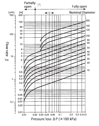
Note (²): Do not use in partial opening (pressure loss ΔP ≤ 2 kPa or 5 kPa), as there is a possibility of chattering.
- The graph lines show the case of water at 20°C.
- To estimate the pressure loss for other fluids, read the graph value using the equivalent flow rate:
Vw = V × ρ / 1000
Where:
Vw = Equivalent flow rate (ℓ/s or m³/h)
ρ = Fluid density (operating) (kg/m³)
V = Actual flow rate (operating) (ℓ/s or m³/h) - The graph assumes horizontal piping unless otherwise stated.
- In vertical piping, there may be slight differences before the valve is fully opened, but once fully opened (normal flow state), the same conditions apply as for horizontal piping.
Related Products
-
Fushiman GH5 type/GH5M type temperature control valve
-
Fushiman LCD2 type/LCD3 type liquid level adjustment valve
-
Fushiman P100-2F Pressure Reducing Valves
-
Fushiman RMD31D type differential pressure valve for liquids
-
Fushiman B260 type back pressure valve for steam
-
Fushiman P260-1LFA Remote Adjusted Pressure Reducing Valves
REQUEST QUOTATION

PAYMENT

LINK


