Fushiman Co.
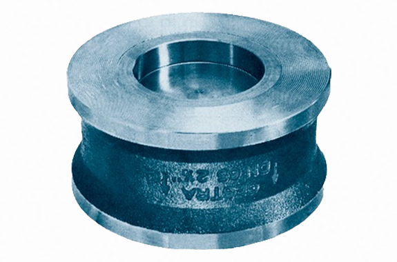
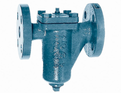
Fushiman RK26A type check valve
Manufacturer: Fushiman Co.,LTD.
Model: RK26A
| Model | Nominal diameter | Fluid | Maximum Operating Pressure | Maximum Operating Temperature | Body Material | Connection |
|---|---|---|---|---|---|---|
| RK26A | 15–100 | Steam Gas Liquid | 4.22 MPa | 300°C | Austenitic stainless steel (equivalent to SUS316) | Wafer |
Wafer type, compact, and lightweight — installation orientation is optional.
We also manufacture valve bodies in stainless cast steel (RK16A type). (Note: Cv values and pressure loss may differ slightly.)
Specifications
| Model | RK26A | |||||||
| Description | The maximum operating pressure and temperature for metal seat valves vary depending on the flange standard. Valves for use above 300°C are also available. | |||||||
| Type of Disc Contact Surface | Metal Seat | Soft Seat | ||||||
| Applicable Fluid | Liquid, gas, and steam | Water, condensate, and steam | Mineral oil | Gas and air | ||||
| Maximum Operating Pressure (MPa) | 4.22 | 3.57 | 3.16 | 4 | 4 | 4 | 5.7 | |
| Maximum Operating Temperature (°C) | 100 | 200 | 300 | 120 | 120 | 120 | 160 | |
| Material | Disc | Stainless Steel | EPDM | Fluororubber | ||||
| Body & Seat (Integral) | Austenitic Stainless Cast Steel | |||||||
| Spring | Stainless Steel | |||||||
| Pipe Connection: Compatible Flanges | Wafer Type: DIN PN 10/16/25/40, ASME Class 150/300 RF | |||||||
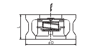
Structure and Dimensions
| Model | RK26A | |||||||||||
| Nominal Diameter | 15 | 20 | 25 | 32 | 40 | 50 | 65 | 80 | 100 | |||
| Dimensions | L | 25 | 31.5 | 35.5 | 40 | 45 | 56 | 63 | 71 | 80 | ||
| D | ASME Class 150 RF | 46 | 56 | 66 | 75 | 85 | 104 | 123 | 135 | 173 | ||
| ASME Class 300 RF | 52 | 63 | 72 | 81 | 93 | 108 | 128 | 147 | 179 | |||
| DIN PN 10–40 | 52 | 63 | 72 | 81 | 93 | 108 | 128 | 143 | PN 10/16:163 PN 25/40:169 | |||
| Opening Pressure | Installation Orientation | Without Spring | ↑ | 0.25 | 0.25 | 0.25 | 0.35 | 0.40 | 0.45 | 0.50 | 0.55 | 0.65 |
| With Spring | ↑ | 1.00 | 1.00 | 1.00 | 1.20 | 1.30 | 1.40 | 1.50 | 1.60 | 1.80 | ||
| → | 0.75 | 0.75 | 0.75 | 0.85 | 0.90 | 0.95 | 1.00 | 1.05 | 1.15 | |||
| ↓ | 0.50 | 0.50 | 0.50 | 0.50 | 0.50 | 0.50 | 0.50 | 0.50 | 0.50 | |||
| Cv Value | 4.3 | 7.9 | 12 | 18 | 27 | 43 | 68 | 90 | 135 | |||
| Weight | 0.25 | 0.40 | 0.57 | 0.83 | 1.20 | 2.15 | 3.20 | 4.50 | 6.90 | |||
Note: The allowable tolerance for opening pressure is ±20%. Do not use for pressure regulation purposes.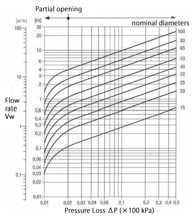
Note (1):
In partial opening conditions (when pressure loss ΔP is 2 kPa or less), chattering may occur. Do not use under such conditions.
- The lines in the graph show water at 20°C.
- To determine pressure loss for other fluids, use the following formula to calculate the equivalent water flow rate, then read from the graph:
Vw = V × ρ / 1000
Vw: Equivalent water flow rate (ℓ/s or m³/h)
ρ: Fluid density (operating) (kg/m³)
V: Actual flow rate (operating) (ℓ/s or m³/h) - The graph assumes horizontal piping unless otherwise noted.
- In vertical piping, the valve may behave differently until it is fully open, but once fully open (normal flow), it functions the same as in horizontal piping.
Related Products
REQUEST QUOTATION

PAYMENT

LINK


