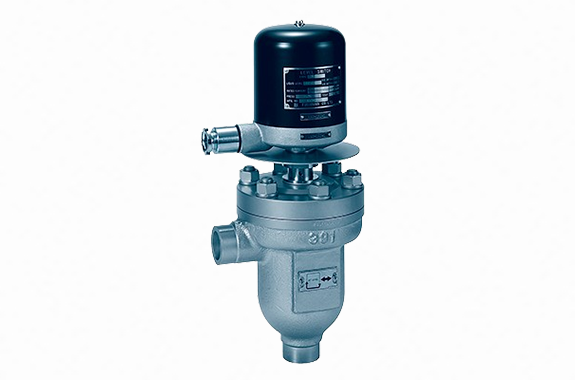
Manufacturer: Fushiman Co.,LTD.
Model: SLG
| Model | Nominal Diameter | Maximum Operating Pressure | Maximum Operating Temperature | Body Material | Connection |
|---|
| SLG | 25 | 2.0 MPa | 215°C | FC, SCPH | Flange Socket Weld |
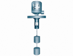
Level switches are used in power plants, geothermal plants, etc., to send level adjustment signals and/or warning signals for high-temperature, high-pressure vessels.
Installation Example
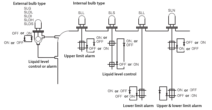
Operation
The rise and fall of the liquid surface are detected by the float, and the switch mechanism in the upper part of the main unit allows confirmation of the signal at the preset water level.
Accuracy / Differential
| Model | Accuracy | Differential |
|---|
| SLS Type | Within ±10 | (150–5550) ±20 |
| SLL Type | Within ±10 | 55 ±20 |
| SLN Type | Within ±10 | 55 ±20 |
| SLG Type | Within ±5 | 10+15/-5 |
| SLDL Type | Within ±7 | 20 ±10 |
| SLDI Type | Within ±7 | 20 ±10 |
| SLDH Type | Within ±7 | 20 ±10 |
| SLDS Type | Within ±7 | 20 ±10 |
Standard Specifications of Main Unit and Float
| Type | Switch Housing Type | Model No. (2)(3) | Fluid Specifications | Nominal Diameter and Pipe Connection | Main Component Materials |
| Maximum Pressure (MPa) | Maximum Temperature (°C)(s) | Minimum Liquid Specific Gravity | Body | Float |
| Dome Type | Drip-proof / Waterproof Type | SLS○ | 1.0 | 100 | 0.8 | 100A — Flange JIS 10K | Cast Iron
Carbon Steel Mild Steel | Stainless Steel |
| SLL○ |
| SLN □ |
| External Type | Drip-proof / Waterproof Type | SLG ○ | 1.0 | 184 | 0.85 | 25A — Flange JIS 10K | Cast Iron | Stainless Steel |
| 2.0 | 215 | 0.85(4) | 25A — Flange JIS 20K 25A — Socket Welding | Cast Steel |
| SLDL ○ | 2.0 | 215 | 0.8 | Cast Steel |
| SLDI ○ | 6.3 | 279 | 0.75 | 25A — Socket Welding |
| SLDH ○ | 10.0 | 310 | 0.7 |
| SLDS ○ | 14.3 | 337.3 | 0.618 | Carbon Steel |
Note:
- Based on JIS C 0920-1993.
- A switch type number is entered in the circle or square on the model. For ○, enter 3 or 4. For □, enter 6 or 8.
- Type 3 uses one SPDT micro switch. Type 4 uses two. Type 6 uses two micro switches (one at each of the two upper and lower stages of the switch mechanism). Type 8 uses two micro switches at both upper and lower two stages.
- Usable even with specific gravity above 0.8.
- Maximum operating temperature indicates the temperature of the liquid.
- SLDI and SLDH types are also available with flange connection.
Operating Fluid Pressure and Temperature Range for Each Level Switch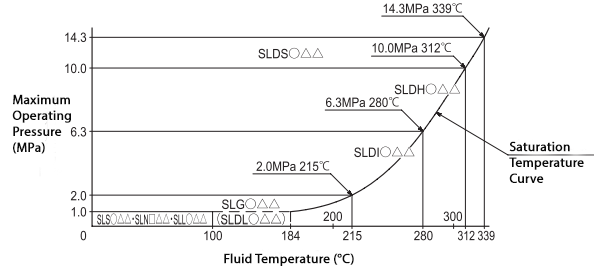
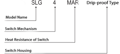
A switch model number is inserted into the ○ and □ symbols in the model name.
For ○, it will be 3 or 4; for □, it will be 6 or 8.
For △△, depending on the switch’s ambient temperature, the following codes will be used:
SA, MA, HA, MAR, HAR (for AC use), SD, MD (for DC use).
Note: For conditions of 2.0 MPa and 215°C or less, SLG ○△△ type is the standard.
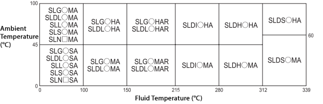
Selection of Switch Mechanism Based on Fluid Temperature and Ambient Temperature
This table shows cases for drip-proof and waterproof switch housings.
Note:
- In the model name, SA indicates a switch for normal temperature, MA for medium temperature, and HA for high temperature.
- For DC use, please read SA as SD and MA as MD.
External Float Type Dimensions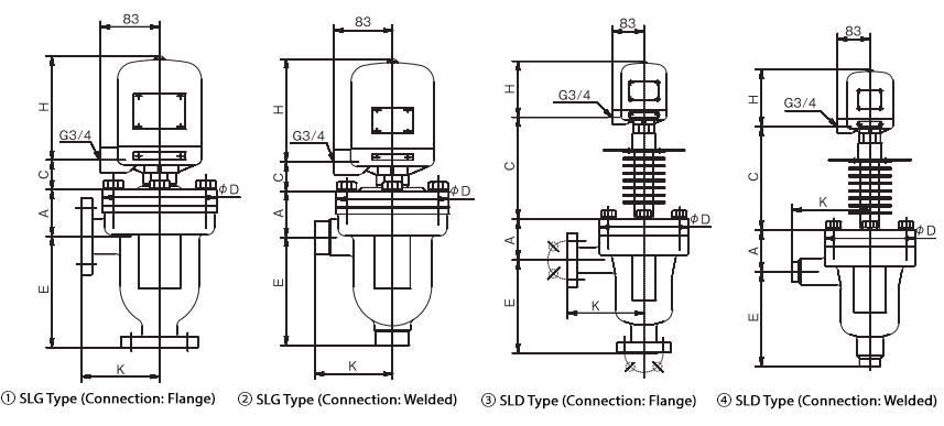
Note: For dimensions H and C, please refer to the switch housing.
Internal Float Type Dimensions
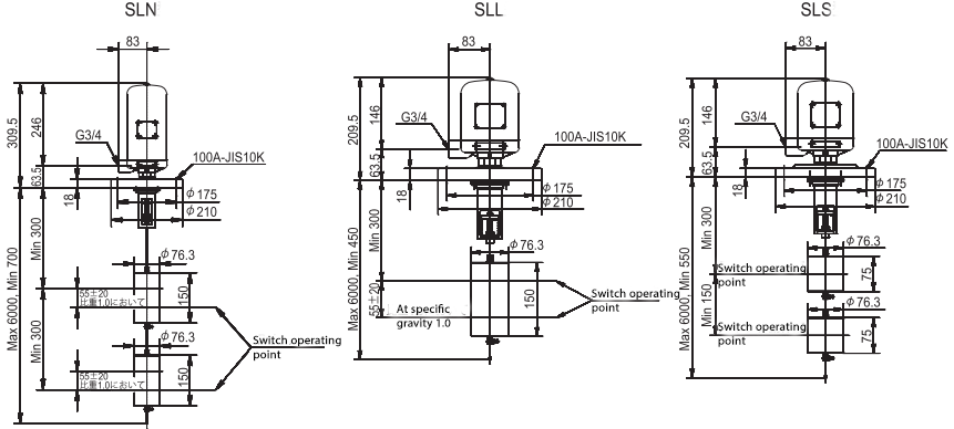
Dimensions of Switch Housing
Drip-proof type
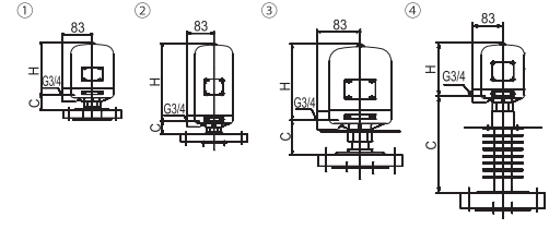
● Drip-proof type (This is the standard type)
(For indoor use) In accordance with JIS C 0920-1993.
…When properly installed, the unit can withstand continuous water spray from all directions within 180 degrees from vertical for 10 minutes without allowing water ingress that would interfere with normal internal operation.
Waterpro of type
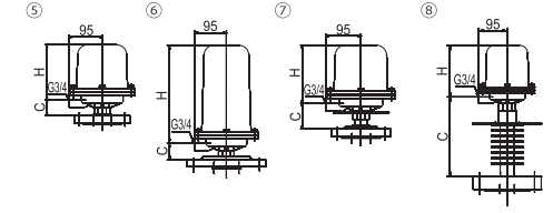
● Waterproof type (For outdoor use)
In accordance with JIS C 0920-1993.
…When properly installed, the structure can withstand water sprayed continuously for 15 minutes from all directions using a nozzle with an inner diameter of 12.5 mm and a water head of 10 meters, without any signs of water ingress inside.
| Drip-proof Type | Waterproof Type |
|---|
| Switch Housing No. | Applicable Model | Dimensions (H) | Dimensions (C) | Switch Housing No. | Applicable Model | Dimensions (H) | Dimensions (C) |
|---|
| ① | SLG○SA, MA, HA (10K)
SLG○SA, MA, HA (20K)
SLDL○SA, MA, HA
SLL○SA, MA
SLS○SA, MA | 146 | 45.5 / 41.5 / – / – / 45.5 | ⑤ | SLG○SA, MA, HA (10K)
SLG○SA, MA, HA (20K)
SLDL○SA, MA, HA
SLL○SA, MA
SLS○SA, MA | 158 | 45.5 / 41.5 / – / – / 49.5 |
| ② | SLN□SA, MA | 246 | – | ⑥ | SLN□SA, MA | 258 | – |
| ③ | SLG○MAR, HAR (10K)
SLG○MAR, HAR (20K)
SLDL○MAR, HAR | 146 | 69.5 / 65.5 / 66.5 | ⑦ | SLG○MAR, HAR (10K)
SLG○MAR, HAR (20K)
SLDL○MAR, HAR | 158 | 73.5 / 69.5 / – |
| ④ | SLDI○MA, HA
SLDH○MA, HA
SLDS○MA, HA | 146 / 206 | 264 / 192 | ⑧ | SLDI○MA, HA
SLDH○MA, HA
SLDS○MA, HA | 158 / 258 | 268 / 196 |
Note: In the model name, ○ indicates 3 or 4, and □ indicates 6 or 8.
Switch Mechanism Ratings
| Model | Max Operating Temp | Contact Rating – Resistive Load | Contact Rating – Inductive Load |
|---|
| SA | 70°C | AC125V, 250V: 15A
DC125V: 0.5A
DC250V: 0.25A | AC125V, 250V: 10A
DC125V: 0.05A
DC250V: 0.03A |
| MA | 120°C | AC125V, 250V: 15A
DC125V: 0.5A
DC250V: 0.25A | AC125V, 250V: 15A
DC125V: 0.05A
DC250V: 0.03A |
| HA | 260°C | AC125V, 250V: 1A
DC30V: 1A
DC125V: 0.5A | AC125V, 250V: 1A
DC30V: 1A
DC125V: 0.4A |
| SD(2) | 70°C | DC125V: 10A
DC250V: 3A | DC125V: 6A
DC250V: 1.5A |
| MD(2) | 120°C | DC125V: 10A
DC250V: 3A | DC125V: 6A
DC250V: 1.5A |
SA, MA, and HA use AC micro switches. (They can also be used for DC.)
For high-capacity DC use, there are SD and MD.
Note that a DC switch mechanism corresponding to HA is not manufactured.
Note (1): This temperature indicates the temperature applied to the switch. It is not the fluid temperature.
(2): Can be used with AC (alternating current) under the same electrical rating as DC (direct current).
Selection of Switch Mechanism
The switch uses a micro switch.
| Switch Mecha No. | Configuration | Application |
|---|
| ③ | 1 set of switch mechanism with 1 micro switch | Used in SLG, SLDL, SLDI, SLDH, SLDS, SLS, SLL models |
| ④ | 1 set of switch mechanism with 2 micro switches | Used in SLG, SLDL, SLDI, SLDH, SLDS, SLS, SLL models |
| ⑥ | 2 sets of switch mechanism with 1 micro switch each | Used in SLN model |
| ⑧ | 2 sets of switch mechanism with 2 micro switches each | Used in SLN model |
Selection Based on Fluid Temperature and Ambient Temperature
Select by considering the heat resistance of the micro switch.
Please refer to page 251 for “Operating Fluid Pressure and Fluid Temperature Range for Each Level Switch” and “Selection of Switch Mechanism Based on Fluid Temperature and Ambient Temperature”.
(Note: For SLL, SLS, and SLN types, only SA and MA are applicable.)
The specifications of the switch mechanism vary depending on the maximum operating temperature (heat resistance).
Please refer to page 253 for “Specifications of Switch Mechanism”.
Model Selection
Selection Example
Specification:
For indoor use, mounted on a tank.
Liquid level, upper limit alarm, pump stop.
Pressure: 0.2MPa, Temperature: 214°C, Specific gravity of liquid: 0.85, Ambient temperature: Normal
- Based on mounting method (e.g., ball float type), pressure, temperature, specific gravity check → Refer to page 251 “Specifications” and “Operating Pressure and Fluid Temperature Range for Each Level Switch” → SLG
- Required switch mechanism → Refer to page 254 “Switch Mechanism Selection” → 2-contact type → 4
- Switch heat resistance → Refer to page 251 “Selection of Switch Mechanism Based on Fluid and Ambient Temperature” → MAR
- Mounting location is indoors → switch housing type is drip-proof.
Thus, the model becomes: SLG4MAR Drip-proof Type