Fushiman Co.
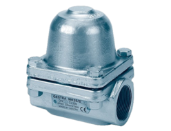
Fushiman LCD2 type/LCD3 type liquid level adjustment valve
Manufacturer: Fushiman Co.,LTD.
Model: LCD2
| Model | Nominal Diameter | Maximum Operating Pressure | Maximum Operating Temperature | Body Material | Connection |
|---|---|---|---|---|---|
| LCD2 | 25–100 | 1.0 MPa | 185°C | FC, SCPH2, SCS | Flanges |
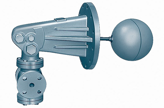
The LCD-type liquid level control valve automatically adjusts the water level in towers, tanks, and boilers by adding or reducing feed water and drain. Despite not using any auxiliary power sources such as electricity or air, it is widely used and highly regarded for its excellent control performance.
Features
The float (detection part) and the valve (control part) are directly connected, and the simple structure allows for direct mounting to a tank, making handling easy and offering excellent durability.
Performs precise and responsive water level adjustment without requiring auxiliary power, which is often a cause of malfunction.
Uses a valve structure without packing, which can cause friction or leakage, enabling reliable performance even with small manual operation force, without auxiliary power.
By removing the inspection hole plug, the internal mechanism can be inspected while the unit remains installed on the tower, tank, or boiler.
Specifications and Performance
| Type | Internal Ball Type | External Ball Type | ||
| Model | LCD2 | LCD3 | LCD3 | |
| Category | Outlet Type | Inlet Type | Outlet Type | Inlet Type |
| Nominal Diameter | 25–100 mm | |||
| Max Primary Pressure | 1.0 MPa | |||
| Max Operating Temperature | 185°C | |||
| Valve Body Material | Cast Iron | |||
| Valve & Seat Material | Stainless Steel | |||
| Float Material | Stainless Steel | |||
| Viscosity | 200 mm²/s max | |||
| Specific Gravity | 0.9 or higher | |||
| Valve Connection | Flange JIS 10K | |||
| Min Adjustable Flow | 10% of rated flow | |||
| Valve Leakage | 0.5% or less of rated flow | |||
Note: We also manufacture valve bodies and main units made of cast iron with nylon coating and stainless-clad steel.
Outlet Type: When the liquid level in the tank rises, the valve opens (float rises) and discharges fluid outside the tank to maintain a constant liquid level.
Inlet Type: When the liquid level in the tank falls, the valve opens (float lowers) and supplies fluid into the tank to maintain a constant liquid level.
Maximum Allowable Differential Pressure / Cv
| Nominal Diameter (mm) | 25 | 40 | 50 | 65 | 80 | 100 |
|---|---|---|---|---|---|---|
| Max Allowable Differential Pressure After Valve (MPa) | 0.9 | 0.7 | 0.6 | 0.45 | 0.4 | 0.3 |
| Rated Cv Value | 6 | 10 | 16 | 23 | 35 | 50 |
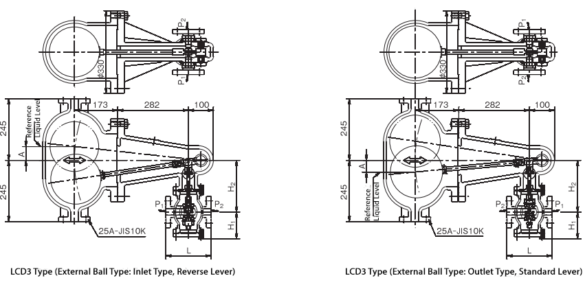
Dimensions & Weight
| Nominal Diameter (mm) | 25 | 40 | 50 | 65 | 80 | 100 |
|---|---|---|---|---|---|---|
| L (mm) | 180 | 195 | 200 | 220 | 250 | 310 |
| H₁ (mm) | 107 | 117 | 117 | 122 | 145 | 160 |
| H₂ (mm) | 207 | 217 | 217 | 222 | 244 | 259 |
| Weight (kg) – LCD2 Type | 48 | 52 | 52 | 60 | 135 | 140 |
| Weight (kg) – LCD3 Type | 88 | 95 | 95 | 100 | 175 | 180 |
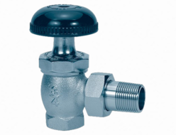
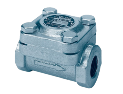
Installation Example 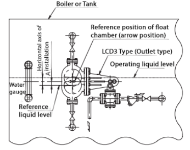
Note: The assembly orientation of the float chamber and valve box in the diagram differs from the photo shown above.
Structure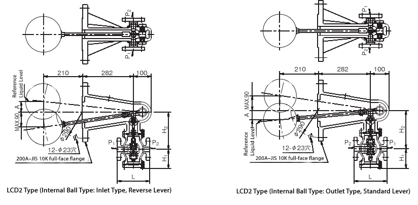
 Operation
- The system consists of three main parts: a float and body that detect the water level, a lever mechanism that transmits the float movement to the valve as operating force, and a valve box that adjusts the outflow/inflow based on changes in the water level.
- A standard lever is used to control outflow, while a reverse lever is used to control inflow.
- In the outlet type, when the water level rises, the float and lever rise, opening the valve with the standard lever, which increases the outflow and acts to lower the water level. When the water level falls, the valve closes, reducing outflow and acting to prevent further decrease in water level.
- In the inlet type, when the water level falls, the float and lever lower, opening the valve with the reverse lever, which increases inflow and acts to raise the water level. When the water level rises, the valve closes, reducing inflow and preventing the water level from rising further.
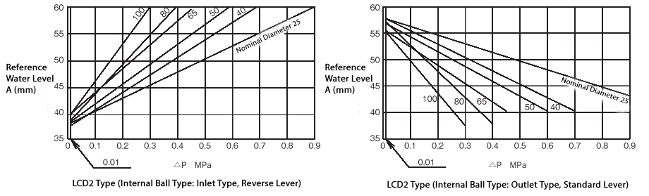
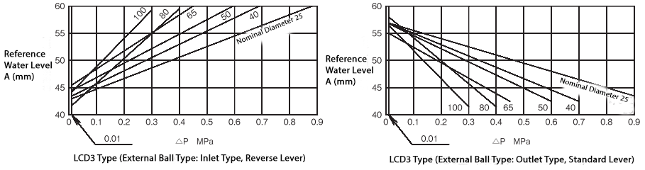
Reference Water Level A
The relationship between the reference water level A and the differential pressure before and after the valve is as shown in the following diagram.
Notes When Selecting
- The liquid level control valve should not be oversized or undersized. Proper results cannot be obtained if it is not correctly sized. Please calculate the Cv value and select the appropriate nominal diameter.
- LCD-type liquid level control valves will not operate properly if the differential pressure before and after the valve is too large due to their self-operated design.
- The Cv value is calculated based on pressure loss through the valve, but actual conditions may differ. Please consider the purpose of the liquid, pressure, viscosity, and allowable pressure loss based on piping diameter, pipe length, and pump capacity.
- There are two types of control methods: inlet control and outlet control. The internal structure and components are the same, and by changing the assembly method, either method can be used. For safety and long-term reliability, please select the appropriate method based on system design.
Notes When Making Inquiries
When inquiring about liquid level control valves, please provide the following information:
- Control method — will it control inlet or outlet flow?
- Purpose of the valve and the liquid used.
- Valve body type (LCD2 or LCD3), installation position, temperature (maximum, normal, minimum), and viscosity.
- Maximum allowable pressure loss at full open.
- Rated flow rate and minimum controllable flow rate.
- Materials that come in contact with the fluid (valve body, float, lever, plug, etc.).
- Connection specifications.
- Any other special requirements.
Related Products

REQUEST QUOTATION

PAYMENT

LINK


