Suntest
Suntest GYPE2K Probe
Manufacturer: Suntest Co.,Ltd
Model: GYPE2K
Magnetostrictive Displaiacement Transducer
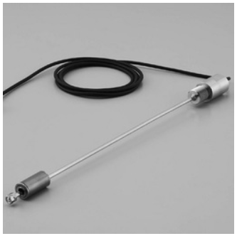
 Model GY Series are “Displacement Transducers” employing magnetostrictive phenomena, especially the Wiedemann effect. An ultra-sonic wave is generated by a moving magnet operating near a magnetostrictive wave guide on which the sonic wave propagates up to the head of the transducer.
The propagation time is precisely measured by state of the art technology and then the absolute displacement transducer is operational.
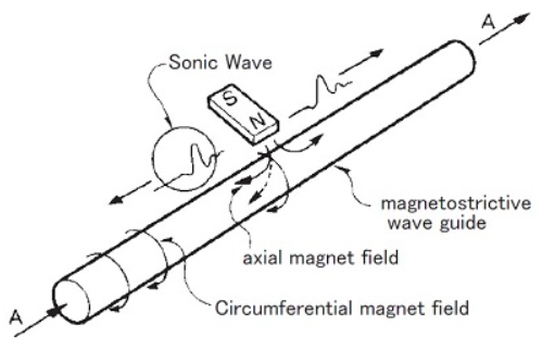
[ Principle ]
The figure shows the fundamental principle of operation.
When a current pulse like A is given to the wave guide, it generates a circumferential magnetic field on the wave guide, then placement of the movable magnet (polarized axially) as shown, only the axial magnetic field of the magnet affecting the wave guide produces a resultant field as indicated by the dotted line.
The vector combination of these two fields produces torsional strain, a phenomenon known as the Wiedemann Effect.
It is a form of vibration and propagates along the wave guide in the form of a transverse ultra-sonic wave.
The GY series displacement transducers detect the propagation time of the ultra-sonic wave.
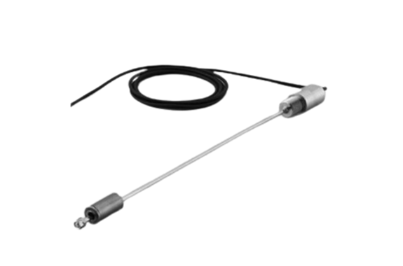
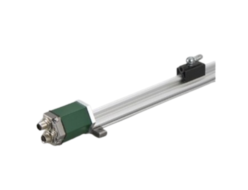
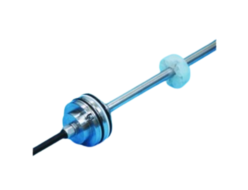
GYPE2K Probe.
Probe rod Φ4
The GYPE2K probe is a sensor characterized in a fine rod
and a small head.
A fine rod (outside diameter Φ4) and a small head expand
the design flexibility of the equipment.
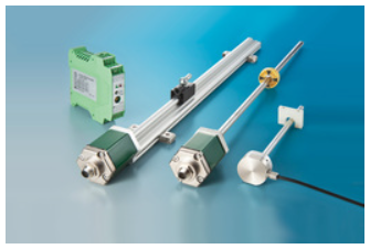
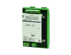
◆Associated controller
- Analogue output:GYHC
- Digital output:GYDC-S1, GYDC-05
Specifications
| Non-linearity | ≦±0.05%FS Typ. |
|---|---|
| Resolution | ( Analogue ) ≦0.03%FS ( Digital ) 0.1mm |
| Repeatability | ≦±0.03%FS |
| Temp. drift | ≦±0.01%FS / °C |
| Max. Pressure | 18MPa ( probe rod, static for 10 min. ) |
| Operating temp. | -20°C〜+80°C |
| Storage temp. | -40°C〜+80°C |
| Vibration | 3G ( or 40Hz 1mmPP ) |
| Shock | 20G ( 2msec ) |
| IP grade | IP64 |
- The above mentioned accuracy applies to sensors with an effective stroke of 100mm or more.
- The specification of stroke less than 100mm is equal that of stroke 100mm.
Model No.

① Effective stroke
15〜250mm
② Head dead zone
35 : 35mm ( No.Φ magnet )
28 : 28mm ( Ti float )
□ :□mm ( option ) ( specified by customers )
・Possible Min. length depends on the selected magnet or float.
③ Tip dead zone
30 : 30mm ( No.Φ magnet )
42 : 42mm ( Ti float )
□ :□mm ( option ) ( specified by customers )
・Possible Min. length depends on the selected magnet or float.
④ Thread / Rod diameter
Y4 :M18xP1.0, rod Φ4 (Std.)
⑤ Associated magnet or float
| magnet | float |
|---|---|
| MG0 :No.Φ (Std.) | FL21 :Ti |
・This model code means only specifying associated magnet or float.
・Ordering magnet or float individually.
⑥ Cable connection
G□F :pigtail / cable end : free
G□A :pigtail / cable end : with connector for relay
( □:cable length (m))
・Cable length is Max. 5m and the specified length can not be changed
at user’s side. Not possible to make it short or add extend cable.
It is possible to cut cable and attach terminal stand or relay connector
without changing total cable length.
・Please confirm extension cable on page 120〜122.
⑦ Output
00 :depends on external controller
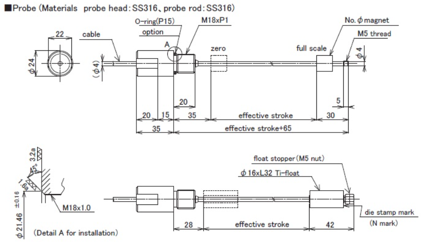
Dimensions
Probe
 Cable (robot cable)
| Wire color | Function |
|---|---|
| shield | shield |
| white | sensor signal |
| black | 0V |
| red | sensor power |
- shield should be connected to shield terminal of the controller.
Ti float
| φ16xL32 Ti float | |
|---|---|
| Volume | 5.31 cm³ |
| Mass | 4.17 g |
| Float gravity | 0.79 (±0.03) |
| Pressure | 2 MPa |
| Material | Ti (titanium) |
Because of the float φ16, it is possible to install it in the container with the probe of which thread is M18.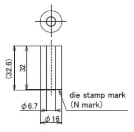
- The M5 screw installed in the rod tip can be used as float stopper or to fix the sensor.
- When the sensor rod part is to be sealed, O ring should be used, refer to detail A drawing.


REQUEST QUOTATION

PAYMENT

LINK


