Meidensha Corporation
Meidensha Protective Relays For Switchgear

Manufacturer: Meidensha Corporation
Features
We have a selection of switchgear protective relays to best suit intended applications. All series are digitalized. A self-diagnosis function displays the details of an abnormality detected in the product, allowing a prompt appropriate countermeasure to be taken.
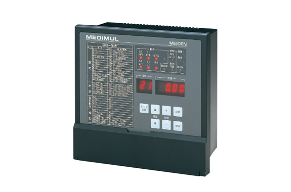
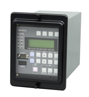
MEIDEN multi-function digital relay
High performance and high functional digital relay offering excellent cost performance JEC2500 compliant and B402 applicable
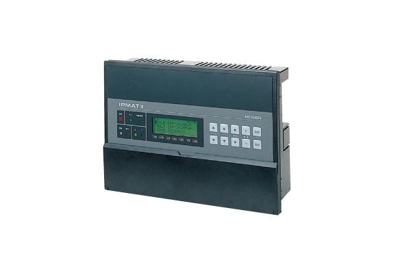
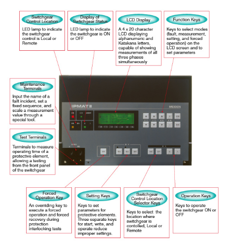
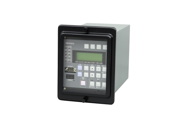
MEIDEN High-performance multi-function digital relay
A multi-function all-digital relay, providing protection, monitoring, control, and measuring functions
JEC2500 compliant and B402 applicable
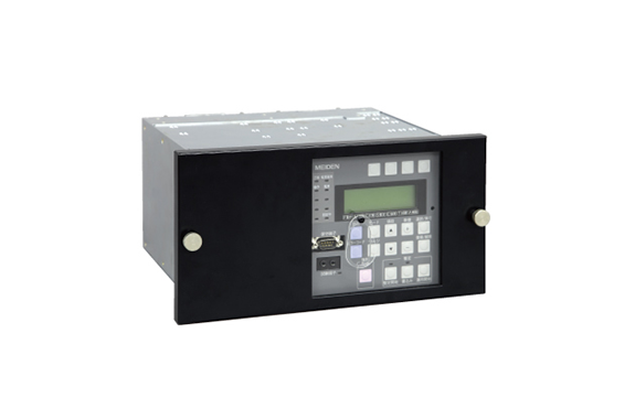
MEIDEN MRR Series unit type digital relay
High functional compact digital relay with smooth renewal capability
JEC2500 compliant and B402 applicable
Applications
MEIDEN multi-functional digital relay network systems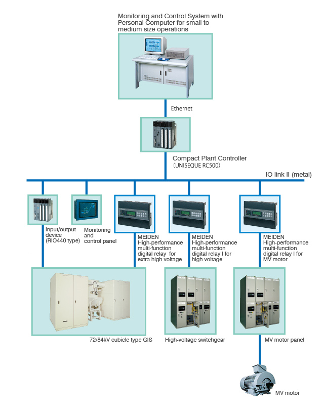
MRR Series Digital Relays
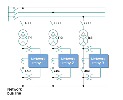
1. Spot Network Relay
A relay for protecting and controlling incoming power equipment in a spot network, incorporating such functions as reverse power shut-off, differential voltage closing operation, non-voltage closing operation, and overcurrent protection
Applicable also to a system with a cogeneration system linked to a network bus lines.
Typical applications
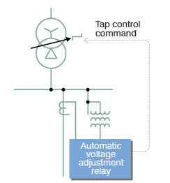
2. Voltage Adjustment Relay
A relay that gives control commands to a tap changer during an on-load operation to maintain the desired voltage level.
*This relay works even at a reverse power flow.
Typical applications
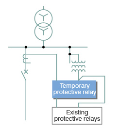
3. Temporary Protective Relay incorporating MRR relays)
This provides a temporary protection through DZ and DG elements when the protective relays are shut down during maintenance, etc.
Typical applications
Specifications
MEDIMULseries(MEIDEN multi-function digital relay)
| Functions | Specifications Current set values for a 5A rated CT only and divide by 5 for a 1A CT | (※) | R1 | R2 | R3 | R4 | B1 | B2 | F1 | F2 | ||
|---|---|---|---|---|---|---|---|---|---|---|---|---|
| HV incoming substations | Main transformer secondary | MV incoming 1 | MV incoming 2 | Bus (for EVT) | Bus (for ZPD) | Feeder (for EVT) | Feeder (for ZPD) | |||||
| Device | Setting range | Operating time | ||||||||||
| Protection elements | 51L | 1.0 to 8.0 A, lock (steps of 0.1 A) | It = 0.5 to 10.0 (steps of 0.1) 3 characteristics (inverse, long, ultra) | 3 | 2 | 2 | 2 | 2 | 2 | |||
| 51H | 1.0 to 80 A, lock (steps of 1 A) | 0.04 to 1.00 s, definite time (steps of 0.01 s) | 3 | 2 | 2 | 2 | 2 | 2 | ||||
| 51G | 0.1 to 2.0 A, lock (steps of 0.1 A) | 0.05 to 1.00 s, definite time (steps of 0.01 s) with malfunction countermeasure against inrush current | ||||||||||
| 27 | 10 to 110 V, lock (steps of 1 V) | 0.05 to 10.00 s, definite time (steps of 0.05 s) | 3 | 3 | 3 | |||||||
| 59 | 100 to 150 V, lock (steps of 1 V) | 0.1 to 10.0 s, definite time (steps of 0.1 s) | ||||||||||
| 64 (EVT) | 3 to 80 V, lock (steps of 1 V) | 0.2 to 30.0 s, definite time (steps of 0.1 s) | ||||||||||
| 64 (ZPD) | 30 to 400 mV, lock (steps of 5 mV) | 0.2 to 30.0 s, definite time (steps of 0.1 s) | ||||||||||
| 67G (EVT) | Io = 1.0 to 6.0 mA, lock ZCT secondary (steps of 0.1 mA) Vo: 3 to 80 V (steps of 1 V) ϕ: Advance of 0 to 80° (steps of 1°) | 0.1 to 2.0 s, definite time (steps of 0.1 s) | ||||||||||
| 67G (ZPD) | Io = 1.0 to 6.0 mA, lock ZCT secondary (steps of 0.1 mA) Vo: 30 to 400 mV (steps of 5 mV) Vo: 3 to 80 V (steps of 1 V) | |||||||||||
| Measuring | Item | Measuring range | Class, response | |||||||||
| Current | CT primary rated current x (0.03 to 1.99) A | Class 1.5, response: 0.5 s | 3 | 3 | 3 | 3 | 3 | 3 | ||||
| Voltage | VT primary rated voltage x (0.03 to 1.40) kV | Class 1.5, response: 0.5 s | 3 | 3 | 3 | |||||||
| Zero phase voltage | 1.0 V to 130.0 V at EVT third voltage | Response: 0.5 s | ||||||||||
| Zero phase voltage | 6.0 to 600.0 mV at ZPD secondary voltage | Response: 0.5 s | ||||||||||
| Maximum zero phase voltage | EVT primary rated voltage x (0.03 to 1.40) kV | Class 1.5 response: 5 cycles | ||||||||||
| Maximum zero phase voltage | ZPD primary rated voltage x (0.03 to 1.40) kV | Response: 5 cycles | ||||||||||
| Leakage current (residual) | CT secondary rated current (A) x (200 to 400) mA | Response: 0.5 s | ||||||||||
| Leakage current (ZCT) | 0.10 to 30.00 mA at ZCT secondary current | Response: 0.5 s | ||||||||||
(*) Type list
| Abbreviations | R1 | R2 | R3 | R4 | B1 | B2 | F1 | F2 |
|---|---|---|---|---|---|---|---|---|
| Application | HV incoming(residual 51 G) | Main transformer secondary,MV generator(for EVT) | MV incoming, MV generator(for ZPD) | MV main transformer secondary | Bus(for EVT) | Bus(for ZPD) | Feeder(for EVT) | Feeder(for ZPD) |
| Type (5 A rating) | MR63M-01 | MR63M-02 | MR63M-03 | MR63M-04 | MB63M-01 | MB63M-02 | MF63M-01 | MF63M-02 |
| Type (1 A rating) | MR63M-01A | MR63M-02A | MR63M-03A | MR63M-04A | MF63M-01A | MF63M-02A |
|  | | ||
| Types | S2 unit | S1 special unit | Built-in device | |
| Product name | Spot network relay | Voltage adjustment relay for distribution substations | Temporary protective relay | |
| Type | MN80S2-01 | MT80S1-01/01A | MR3-1003 | |
| Rating | Current | 5A | 5/√3 / √3A | 5A |
| frequency | 50/60Hz | 50Hz | 60Hz | |
| Normal service conditions | Ambient temperature | Range of performance guarantee: 0 ~ 40°C | ← | ← |
| Range of operation guarantee: -10 ~ 50°C | ← | ← | ||
| Range of recovery guarantee: -20 ~ 60°C | ← | ← | ||
| Relative humidity | 30 ~ 80% | ← | ← | |
| Altitude | 2,000 m or less | ← | ← | |
| Frequency characteristics | Rated frequency = operating value with fluctuation of ±5%: Within ±5% of rated frequency | |||
| Insulation resistance | Between electrical circuits: 5 MΩ Between the whole electrical circuits and casing (earth potential): 10 MΩ Provided that the relative humidity is 80% or less. | ← ← ← | Between electrical circuits: 2 MΩ Between the whole electrical circuits and casing (earth potential): 2 MΩ Provided that the relative humidity is 80% or less. | |
| Withstand voltage | Between electrical circuits: 2000 V for one minute Between the whole electrical circuits and casing (earth potential): 2000 V for one minute | ← ← | ← ← | |
| Lightning impulse withstand voltage | Positive and negative 1.2/50 μs waveforms applied 3 times each. Between control circuits: 3 kV Between the whole electrical circuits and earth: 4.5 kV | ← ← ← | ← Between the whole electrical circuits and earth: 4 kV | |
| Noise immunity | EFT/B tested other than B-402 | ← ← | B-402 tested | |
| Contact capacity | Control outputs | Current capacity 5 A, closing 10 A (0.5 s), opening 0.1 A (DC110 V, R load) | AC 250 V, open/close 1.5 A (inductive load: COS φ = 0.4) | 5 A continuous (max 15 A, 2 seconds) |
| External display | Standstill output open/close 60 mA | ← | Current capacity 5 A, interruption 0.5 A (R load) | |
| Installed relay elements | Main detects | 67L, 67H, 78, 51L/H, 57 27S, 78, 27B, 84S | 90R·L, 59B, 27B | 44SX1, 44SX2, 44SD, 44SR 51D, 51φ 67G, 67GA1, 67GA2, 64 51H, 51A, 51, 51GA, 51G 27B, 64B |
| Fault detects | 67LF, 67HF, 51F, 27SF, 78F, 27BF, 84SF | 59A, 27A | 51DF, 51F, 64F, 51GF, 27F | |
Related Products
-
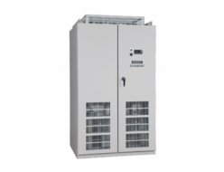
Meidensha Power Conditioner For Solar Power Generation
-
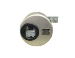
Meidensha Surge Counters With Leakage Current Meter
-
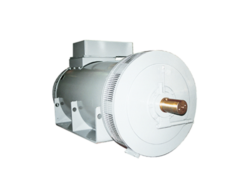
Meidensha Engine Generator Small And Medium Capacity Synchronous Generators
-

Meidensha Large Scale Photovoltaic Power Generating System
-
Meidensha 4 Pole Turbine Generators
-
Meidensha SP1000 Series Power Conditioning Subsystem
REQUEST QUOTATION

PAYMENT

LINK


