MITSUHASHI CORPORATION
MITSUHASHI PGMW-15 Integrated Compact Roll Guide
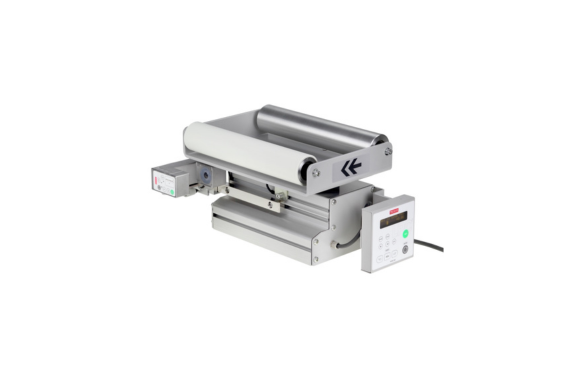
Manufacturer: MITSUHASHI CORPORATION
Model: PGMW-15
This system is used for controlling web trajectory during intermediate web transport processes. Because the controller and sensor are integrated, it reduces the time and effort required for design, installation, wiring, and adjustment, making it easy to use. Equipped with a brushless motor, it offers excellent maintainability and achieves high responsiveness and high-precision control. It is suitable for narrow webs up to 600mm wide and is ideal for controlling trajectory in packaging machines and sanitary product manufacturing machines.
Drawing
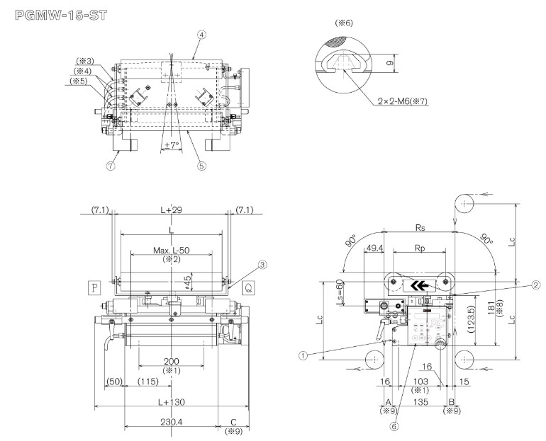 ① Drive unit
② Pivot stand
③ Roll frame
④ Inlet roll
⑤ Outlet roll
⑥ Controller
⑦ Sensor
*1: Mounting pitch *2: Sheet width *3: External control cable *4: Sensor cable *5: Power cable *6: Detailed diagram of mounting nut section (S=1/1) *7: Post-installation spring nut *8: Roll height *9: Dimensions vary depending on size
L: Roll face length Rs: Distance between roll outer diameters Rp: Distance between roll centers Lc: Distance to fixed roll Ls: Distance to sensor
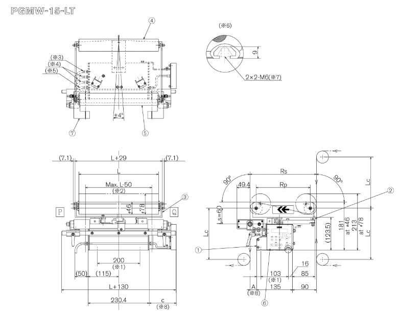
① Drive unit
② Pivot stand
③ Roll frame
④ Inlet roll
⑤ Outlet roll
⑥ Controller
⑦ Sensor
*1: Mounting pitch *2: Sheet width *3: External control cable *4: Sensor cable *5: Power cable *6: Detailed diagram of mounting nut section (S=1/1) *7: Post-installation spring nut *8: Dimensions vary depending on size
L: Roll face length Rs: Distance between roll outer diameters Rp: Distance between roll centers Lc: Distance to fixed roll Ls: Distance to sensor
Features
- Since it only requires connecting the power supply, assembly into the machine can be completed in a short time.
- We have adopted a maintenance-free brushless DC motor.
- It incorporates a ball screw type ultra-compact actuator, which powerfully rotates the roll frame without any wobble.
- The rotational torque of the roll frame is more than 2.5 times greater compared to the conventional gear-type PG-100.
- Combined with low backlash (less than 1/10 of conventional models), the roll frame is supported at three points by the pivot axis and two cam followers, resulting in a highly rigid roll frame.
- You can choose between infrared edge sensors (PSM-75 series) and ultrasonic edge sensors (PSM-46 series) depending on your application. Furthermore, centering control is possible by using two PSM-75 series units.
Specification
| Short Type (PGMW-15-ST) | Long Type (PGMW-15-LT) | ||||||||
| power supply | Connect to the terminals of the included 5m cable (DC24V±20%). (24V: “+”, OV: “-“, Ground: “FG”) | ||||||||
| Current consumption | 0.6A (at DC24V power supply voltage) | ||||||||
| Embedded devices | controller | PEM-200 | |||||||
| sensor | Please specify the type and number of sensors. • PSM-46, 46W (maximum 1 unit, edge control) • PSM-75, 75W (maximum 2 units, edge or centering control) When using the PSM-75 series, it is effective to use a dust blow unit to prevent dust from adhering to the lens in dusty environments. The model number is PSM-75W-DB. In that case, please prepare an air pressure of 0.2-0.5 MPa, dry air, and a maximum consumption of 20 Nℓ/min. | ||||||||
| Scope of application | Roll surface length | 150-650mm | 200-650mm | ||||||
| Roll diameter | Please inquire about other specifications such as φ46, φ78, etc. | ||||||||
| Roll material | • Aluminum roll (anodized/non-anodized) • Rubber roll (NBR white) • CFRP (rubber cork wrapped/non-anodized) Please inquire about other specifications. | ||||||||
| Rollspan | 150mm | 175mm | 200mm | 225mm | 250mm | 275mm | 300mm | 400mm | |
| Correction amount *1 | ±17mm | ±19mm | ±22mm | ±25mm | ±16mm | ±18mm | ±20mm | ±27mm | |
| correction speed | 20mm/s | 22mm/s | 25mm/s | 28mm/s | 14mm/s | 15mm/s | 17mm/s | 23mm/s | |
| Maximum web tension *2 | 200N (Web width 250 mm) | 260N (web width 450 mm) | |||||||
| Maximum web speed | 300m/min | ||||||||
| Usage environment | Temperature: 0-40°C; Humidity: 80% Rh or less (non-condensing) | ||||||||
| Mass (excluding drive unit body and roll frame) | 4.0kg | ||||||||
| others | <Regarding the positioning method of the roll frame> – The center position is determined by a proximity switch, and the stroke end position is determined by an electronic counter (the position is set by the controller). It automatically moves to the center when the power is turned on. (Standard specification) – A proximity switch for stroke end detection can be added as an option. <Regarding the position of the control panel and connector panel> – The control panel and connector panel are located on the left and right sides of the main drive unit case. – The units are shipped in a specific orientation depending on the direction of web flow. (Right flow) When facing the exit roll, the control panel is on the left end. (Left flow) When facing the exit roll, the control panel is on the right end. | ||||||||
*1 This value is calculated from the swing angle of the roll frame.
(Short type: ±7°, Long type: ±4°)
*2 Tension is proportional to the web width.
Related Products
REQUEST QUOTATION

PAYMENT

LINK