SUNCO
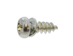
30-N100 (+) B Tite Pan Head (Nitto)
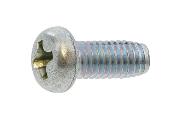
Model: 30-N100
Dia range:M2.6~M4
Length range:6~12
Iron (or standard).
Trivalent zinc cr+3 color white.
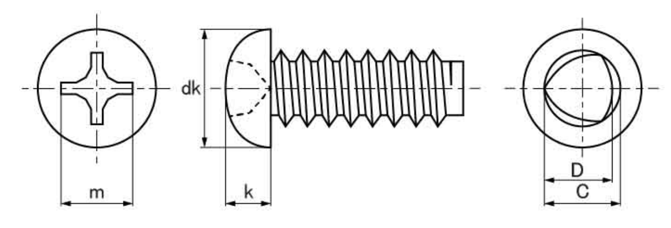
Thread Dimensions ・ Strength
| Nominal Diameter | Pitch (threads/inch) | Thread Diameter | Point Section | Tapered Section Length y mm | Body Breaking Torque N ・ m | Tensile Load KN | |||||
|---|---|---|---|---|---|---|---|---|---|---|---|
| C mm | D mm | C’ mm | |||||||||
| Max | Min | Max | Min | Max | Min | Max | Min | Min | Min | ||
| 2 | 40 | 2.04 | 1.96 | 1.96 | 1.88 | 1.46 | 1.26 | 1.6 | 1.2 | 0.40 | 1.17 |
| 2.3 | 32 | 2.34 | 2.26 | 2.26 | 2.18 | 1.76 | 156 | 2.0 | 1.5 | 0.60 | 1.47 |
| 2.6 | 28 | 264 | 2.56 | 2.55 | 2.47 | 1.94 | 1.74 | 2.3 | 1.8 | 0.97 | 2.05 |
| 3 | 24 | 3.05 | 2.95 | 2.95 | 2.85 | 2.25 | 2.05 | 2.7 | 2.1 | 1.47 | 2.74 |
| 3.5 | 20 | 3.55 | 3.45 | 3.46 | 3.34 | 2.65 | 2.45 | 3.2 | 2.6 | 2.45 | 3.82 |
| 4 | 18 | 4.05 | 3.95 | 3.91 | 3.81 | 3.00 | 2.80 | 3.6 | 2.8 | 3.43 | 4.70 |
| 5 | 16 | 5.06 | 4.94 | 4.90 | 4.78 | 3.74 | 3.44 | 4.0 | 3.1 | 6.46 | 7.15 |
| 6 | 14 | 6.08 | 5.92 | 5.88 | 5.72 | 4.52 | 4.12 | 4.6 | 3.6 | 11.4 | 10.5 |
| B | 12 | 8.10 | 7.90 | 7.85 | 7.65 | 6.00 | 5.50 | 5.3 | 4.2 | 27.8 | 19.2 |
*Tightening rupture torque varies depending on the seating surface resistance, but please consider it to be approximately 50% higher than the body breaking torque.
Proper Pilot Hole Conditions (for Steel)
Unit (mm)
| Engagement Length | |||||||||
|---|---|---|---|---|---|---|---|---|---|
| 0.6 | 0.8 | 1.0 | 1.2 | 1.6 | 2.0 | 2.6 | 3.2 | ||
| Nominal Diameter | 2 | 1.54 | 1.63 | 1.67 | 1.7 | 1.73 | 1.75 | 1.79 | |
| 2.3 | 1.85 | 1.93 | 1.96 | 1.98 | 2.02 | 2.04 | 2.09 | ||
| 2.6 | 2.04 | 2.07 | 2.17 | 2.22 | 2.26 | 2.32 | 2.34 | 2.38 | |
| 3 | 2.34 | 2.40 | 2.44 | 2.56 | 2.62 | 2.68 | 2.72 | 2.75 | |
| 3.5 | 2.70 | 2.79 | 2.86 | 2.92 | 3.07 | 3.10 | 3.18 | 3.21 | |
| 4 | 3.12 | 3.22 | 3.27 | 3.33 | 2.51 | 2.55 | 3.63 | 3.67 | |
| 5 | 4.07 | 4.17 | 4.21 | 4.38 | 4.48 | 4.58 | 4.63 | ||
| 6 | 5.00 | 5.08 | 5.22 | 5.39 | 5.51 | 5.57 | |||
| 8 | 6.77 | 6.88 | 7.00 | 7.13 | 7.36 | 7.52 | |||
*The pilot hole diameters listed above are reference values for steel plates. For materials like aluminum, zinc die-cast, etc., please use these values as a base and select a slightly larger size.
*Tolerance is generally based on ±0.03.
Proper Pilot Hole Conditions (for Resin/Plastic)
Unit (mm)
| Engagement Length | |||||||
|---|---|---|---|---|---|---|---|
| 1.5d | 2.0d | 2.5d | 3.0d | 3.5d | 4.0d | ||
| Nominal Diameter | 2 | 1.65 | 1.68 | 1.71 | 1.73 | 1.75 | 1.77 |
| 2.3 | 1.91 | 1.95 | 1.97 | 1.99 | 2.03 | 2.06 | |
| 2.6 | 2.15 | 2.19 | 2.21 | 2.24 | 2.26 | 2.29 | |
| 3 | 2.49 | 2.51 | 2.54 | 2.59 | 2.65 | 2.68 | |
| 3.5 | 2.94 | 2.97 | 3.03 | 3.10 | 3.14 | 3.17 | |
| 4 | 3.39 | 3.43 | 3.47 | 3.54 | 2.58 | 3.62 | |
| 5 | 4.33 | 4.38 | 4.43 | 4.53 | 4.58 | 4.63 | |
| 6 | 5.27 | 5.33 | 5.44 | 5.51 | 5.57 | 5.57 | |
| 8 | 6.99 | 7.13 | 7.28 | 7.36 | 7.43 | 7.44 | |
*For plastics/resins, an engagement length of 2d or more is generally required.
*Tolerance is generally based on ±0.03.
REQUEST QUOTATION

PAYMENT

LINK


