Daiichi Keiki, Japan
Daiichi Keiki DI Series Digital Pressure Gauge
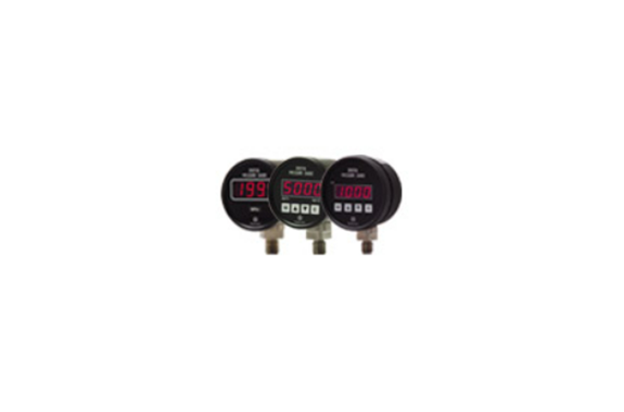
Manufacturer: Daiichi Keiki
Model: DI Series
Overview
The DI series is a digital pressure gauge that allows for both local indication and pressure transmission by replacing existing 2-wire pressure transmitters, utilizing their wiring. Despite being a 2-wire system, it has achieved LED display. (DIT)
As a sensor-integrated digital pressure gauge, it is the first in the industry to adopt a large-capacity mechanical relay (AC250V/8A resistive load). It is ideal for replacing the combination of Bourdon tube pressure gauges and mechanical switches, significantly improving visibility and reliability. (DIM)
Functions
Zero Shift Function
![]()
The Zero Shift function is an automatic zero adjustment feature. When the ▽ key is pressed, all decimal points on the display blink. If you continue to press the ▽ key, after about 3 seconds, the zero point correction value updates, the display reads ‘0’, and measurement resumes. Note that the correction value for the zero shift is backed up and will not be cleared even when the power is turned off.
Tracking Zero Function
![]()
It is a function that digitally and automatically corrects the zero point internally.

Example: Correction time = 3 samplings, Correction value = 3 digits
① After power is turned on, the tracking zero function starts. The display is within the correction range, so it shows “0”.
②③ Since the display is within 3 digits, it is corrected to display “0”.
④ It is outside the correction value, so no correction is made.
⑤ The display is again within 3 digits, so it is corrected to display “0”.
※1 The correction value for tracking zero is not backed up (it is cleared when the power is turned off).
※2 The tracking zero function is a feature that monitors gradual zero point drifts such as those caused by temperature effects on sensor output and automatically corrects them. Be careful not to inadvertently dull the measurement response by increasing the average count setting, as it might unexpectedly perform zero correction depending on the setting.
※3 The correction period can generally be calculated using the following formula: Correction period (in seconds) = Correction time setting / Sampling speed setting
Key Protect Function
![]()
Key Protect Function
This function imposes restrictions on various features to prevent misconfigurations and malfunctions due to inadvertent key operations.
– Restricted functions
- Zero Shift Function (key operations are not accepted)
- Loop Check Function (key operations are not accepted)
- Setting Comparison Data (however, checking is possible)
- Setting Condition Data (however, checking is possible)
Comparison Judgment Function
![]()
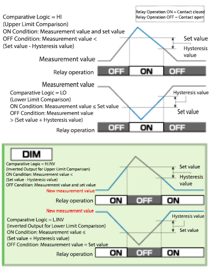
In the setting of comparison logic 「LOG」 within the comparison data settings, the following four types of comparison conditions can be selected.
Analog output scaling function
![]()
You can set two points arbitrarily within the display range (-5000 to 5000). It is possible to output from 4.00 to 20.00 mA corresponding to the analog output Lo. setting value to the analog output Hi. setting value.
Loop check function
You can output any constant current (4.00 to 20.00mA) from the analog output terminal by setting the key, so you can easily check the operation of the control system.
Automatic DZ function
![]()
After the power is turned on, the first measured value is automatically zero-corrected, and subsequent measurements are performed using that as the zero point.
You can enable (on) or disable (off) the condition data “PodZ” setting.
*Auto DZ correction values are not backed up.
(Cleared when the power is turned off.)
Precautions for use
- Do not damage or forcefully bend the power supply wiring, sensor cable, and input/output wires.
- This may cause a short circuit that may cause a fire.
- Do not use it at any other than the specified power supply voltage. Using the product at a different voltage may cause fire, electric shock, or malfunction.
- Do not modify the device or accessories. Doing so may cause fire, electric shock, or malfunction.
- Please make sure to connect the wiring properly. Failure to do so may cause poor contact, resulting in fire, electric shock, or malfunction.
Standard Specifications & Performance
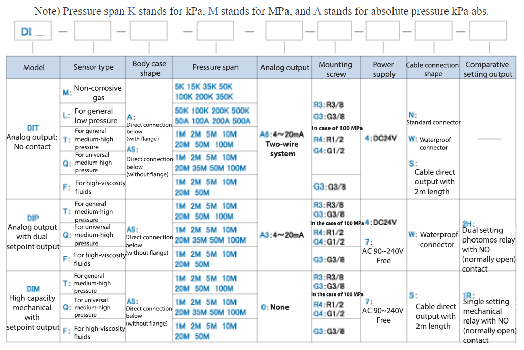
Model number
Specification
| Model number | D.I.T. | DIP | DIM | |
| Display | 1999 3 1/2 digit red LED (character height 14.2mm ) | 4-digit red LED (character height 14.2mm) | ||
| Sampling rate | Approximately 2.5 times/second | 1 to 500 times/sec changeable | ||
| Display conversion speed | 1 to 25 times/sec changeable | |||
| Comparison setting output | Number of output points | – | 2 points (setting values can be set arbitrarily) | 1 point (setting value can be set arbitrarily) |
| Comparison conditions | – | Hi setting: Measured value ≧ Set value = Output ON Lo setting: Measured value ≦ Set value = Output ON (Hi or Lo can be set arbitrarily for each of the two points) | Comparison logic can be selected from [Hi/Lo/H.INV/L.INV] and can be changed | |
| Comparison setting range | – | -5000~5000 | -1999~1999 | |
| Hysteresis setting range | – | 0-999 | ||
| Contact rating | – | Photomos relay output AC/DC combined load voltage 240V load current 120mA or less | Mechanical relay output AC250V/8A (resistive load) | |
| Operating temperature and humidity range | 0 to 50℃, 35 to 85%RH (no freezing or condensation) | |||
| Power supply | 4 : DC24V±10% | 4 : DC24V±10% [4W or less] 7 : AC90 to 240V (free) [6VA or less] | 7 : AC90~240V (free) [6VA or less] | |
| Material | – | Case cover: Aluminum die-cast Front panel: Aluminum material (Surface sheet: Polyester film) | ||
| Accessories | Standard connector plug waterproof connector plug (cable not included) | Waterproof connector plug for power input Waterproof connector plug for output (cable not included) | Input/output cable VCTF-4XO.75m㎡, 1m straight out (tip loose) | |
Sensor type specifications
*RC (Rated Capacity) represents pressure span.
| Model | M : Non-corrosive gas | L : For general low pressure | T : For general medium and high pressure | Q : General-purpose medium and high pressure | F : For high viscosity fluid |
| Pressure span | 5・15・35・50・100・200・350kPa | 50・100・200・500kPa 50・100・200・500kPa abs | 1・2・5・10・20・50・100MPa | 1・2・5・10・20・35・50・100MPa | 1・2・5・10・20・50MPa |
| Nonlinearity | ±0.2%RC (5・15kPa:±0.3%RC/℃) | ±0.2%RC | ±0.2%RC (1MPa: ±0.3%RC) | ±0.8%RC (100MPa: ±1%RC) | ±0.5%RC |
| Hysteresis | ±0.2%RC (5・15kPa:±0.3%RC) | ±0.1%RC | ±0.2%RC (1MPa: ±0.3%RC) | ±0.8%RC (100MPa: ±1%RC) | ±0.5%RC |
| Allowable overload | 200%RC | 300%RC | 150%RC | 150%RC | 150%RC |
| Limit overload | 300%RC | 400%RC | 200%RC | 200%RC | 200%RC |
| Temperature effect at zero point | ±0.02%RC/℃ (5kPa:±0.05%RC/℃) | ±0.02%RC/℃ | ±0.02%RC/℃ | ±0.02%RC/℃ (100MPa:±0.1%RC/℃) | ±0.08%RC/℃ |
| Temperature effect on output | ±0.02%RC/℃ (5kPa:±0.05%RC/℃) | ±0.02%RC/℃ | ±0.02%RC/℃ | ±0.1%RC/℃ | ±0.08%RC/℃ |
| Mounting screw | R3/8 or G3/8B | R3/8 or G3/8B | R3/8 or G3/8B (100MPa: R1/2 or G1/2B) | R3/8 or G3/8B (100MPa: G1/2B) | G3/8B |
| Pressure receiving connection material | Aluminum 2017 (Pressure receiving part: Semiconductor) | SUS316L (Diaphragm: Hastelloy C22) | SUS630 | SUS630 | SUS630 |
Dimensions
Terminal connection diagram


Mounting screw diagram


