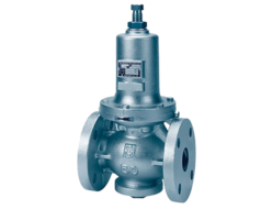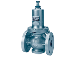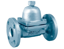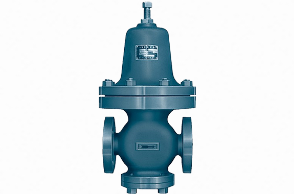
- Simple-structured direct-acting pressure reducing valve.
- Few failures and long lifespan.
- When the diaphragm is made of stainless steel, it can be used for steam, gas, and liquid.
Specifications and Materials
| Pressure MPa | Temperature ℃ | Fluid | Main Component Materials | Pipe Connection | |||||
| Primary Side | Secondary Side Setting Range (¹) | Valve Body | Spring Protection Tube | Lower Cover | Valve & Valve Seat | Diaphragm | |||
| 1.0 MPa or less | (Standard Pressure) 0.03 〜0.055 0.055〜0.085 0.085〜0.13 0.13 〜0.2 0.2 〜0.3 (Medium Pressure) 0.30 〜0.45 0.45 〜0.7 0.7 〜1.0 (High Pressure) 1.0 〜1.6 | 0〜60C)(¹) | Air, water, and other non-corrosive gases and liquids | Cast Iron | Cast Iron | Cast Iron | Stainless Steel | Synthetic Rubber (¹) | Flange JIS 10K Full Face |
| 2.0 MPa or less | Cast Steel | Carbon Steel | Flange JIS 20K Flat Face | ||||||
| Stainless Steel, Cast Steel | Stainless Steel | ||||||||
| 1.0 MPa or less | 0〜220 | Steam and other non-corrosive gases and liquids | Cast Iron | Cast Iron | Stainless Steel | Flange JIS 10K Full Face | |||
| 2.0 MPa or less | Cast Steel | Carbon Steel | Flange JIS 20K Flat Face | ||||||
| Stainless Steel, Cast Steel | Stainless Steel | ||||||||
Notes:
(¹) If the diaphragm is made of synthetic rubber, the set pressure must be 1.0 MPa or less.
(²) Products for temperatures exceeding 60°C and up to 110°C are also available.
Remarks:
ASME Class 150 and 300 products are also available.
Performance
| Offset | 10–20% of the maximum set pressure |
|---|---|
| Valve Seat Leakage | 0.5% or less of the rated flow rate |
| Pressure Reduction Ratio | 10:1 or less |
Cv Value
| Diaphragm Material | Nominal Diameter | Secondary Side Setting Range (MPa) | |||||||
| 0.03 〜0.055 | 0.055〜0.085 | 0.085〜0.13 | 0.13 〜0.2 | 0.2 〜0.3 | 0.3 〜0.45 | 0.45 〜0.7 | 0.7 and above | ||
| Cv (Varies depending on the set pressure range) | |||||||||
| Synthetic Rubber | 15 | 0.40 | 0.78 | 1.30 | 1.71 | 1.55 | 1.74 | 1.75 | 1.75 |
| 20 | 0.42 | 0.82 | 1.38 | 2.11 | 1.79 | 2.20 | 2.28 | 2.28 | |
| 25 | 0.42 | 0.82 | 1.38 | 2.14 | 1.82 | 2.23 | 2.28 | 2.28 | |
| 40 | 0.70 | 1.34 | 2.23 | 3.88 | 2.72 | 3.70 | 3.36 | 3.36 | |
| 50 | 0.79 | 1.50 | 2.52 | 4.44 | 3.65 | 5.35 | 5.12 | 5.12 | |
| Stainless Steel | 15 | 0.08 | 0.15 | 0.24 | 0.78 | 0.96 | 0.96 | 1.08 | 1.08 |
| 20 | 0.09 | 0.17 | 0.28 | 0.79 | 1.02 | 1.02 | 1.11 | 1.11 | |
| 25 | 0.09 | 0.17 | 0.28 | 0.80 | 1.02 | 1.02 | 1.11 | 1.11 | |
| 40 | 0.21 | 0.41 | 0.66 | 1.49 | 1.58 | 1.64 | 2.20 | 2.20 | |
| 50 | 0.35 | 0.69 | 1.10 | 1.88 | 2.09 | 2.09 | 2.20 | 2.20 | |
Remarks: If the offset is 20% or less of the maximum set pressure, the Cv value will be twice the values in the above table. Please refer to page 280 for Cv calculations.
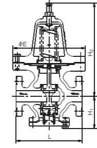
Structure and Dimensions
Dimensions and Weight
| Material / Flange Standard | Nominal Diameter (mm) | L (mm) | H₁ (mm) | H₂ (mm) | E (mm) | Weight (kg) |
| Cast Iron (JIS 10K) | 15 | 186 | 89 | 320 | 225 | |
| 20 | 190 | 89 | 320 | 25 | ||
| 25 | 190 | 89 | 320 | 28 | ||
| 40 | 230 | 113 | 328 | 38 | ||
| 50 | 250 | 127 | 336 | 40 | ||
| Cast Steel / Stainless Steel (JIS 20K) | 15 | 182 | 93 | 320 | 225 | 27 |
| 20 | 186 | 93 | 320 | 27 | ||
| 25 | 186 | 93 | 320 | 30 | ||
| 40 | 226 | 117 | 328 | 40 | ||
| 50 | 246 | 131 | 336 | 45 |
Remarks: Nominal diameter 65 is also available.