| Model | Nominal diameter | Primary measurement pressure range | Maximum operating temperature | Body Material | Connection |
|---|---|---|---|---|---|
| B260 | 15–80 | 0.07 to 1.0 MPa | 220°C | FC, FCD, SCPH | Flanges |
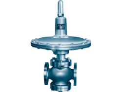
- Compact, lightweight, and high performance.
- Designed for continuous discharge.
- Large capacity.
Specifications and Materials
| Fluid | Primary Side Set Pressure Range (MPa) | Maximum Operating Temperature (°C) | Main Component Materials | Pipe Connection | ||||
|---|---|---|---|---|---|---|---|---|
| Valve Body & Cover | Main Body & Main Valve Seat | Piston & Cylinder | Pilot Valve Body & Pilot Valve Seat | Diaphragm | ||||
| Steam | 0.07~0.2 | 220 | Cast Iron (¹) | Stainless Steel | Stainless Steel | Stainless Steel | Stainless Steel | Flange JIS 10K Full Face |
| 0.1~0.8 | ||||||||
| 0.5~1.0 | ||||||||
Note (¹): The valve body for nominal diameters 15 to 40 is made of ductile cast iron.
Remarks:
- Valve bodies made of cast steel or stainless steel castings are also available.
- ASME Class 150 products are also available.
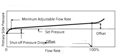
Performance
| Minimum Set Differential Pressure | 10% of Primary Side Pressure (Minimum 0.07 MPa) | ||
| Offset | Set Pressure MPa | 0.07~0.2, 0.1~0.8 | ≤ 0.03 MPa |
| 0.5~1.0 MPa | ≤ 0.05 MPa | ||
| Shut-off Pressure Drop | Set Pressure MPa | 0.07~0.2 | ≤ 0.02 MPa |
| 0.1~0.8, 0.5~1.0 | ≤ 0.04 MPa | ||
| Minimum Adjustable Flow Rate | ≤ 5% of Rated Flow Rate | ||
| Valve Seat Leakage | ≤ 0.05% of Rated Flow Rate | ||
Cv Value
| Nominal Diameter (mm) | 15 | 20 | 25 | 32 | 40 | 50 | 65 | 80 |
|---|---|---|---|---|---|---|---|---|
| Cv Value | 1.1 | 2.5 | 4.5 | 7 | 10.1 | 18 | 28.1 | 40.5 |
Structure and Dimensions
| Nominal Diameter (mm) | L (mm) | H₁ (mm) | H₂ (mm) | K (mm) | Weight (kg) |
|---|---|---|---|---|---|
| 15 | 145 | 81 | 171 | 115 | 8 |
| 20 | 150 | 76 | 176 | 115 | 8.5 |
| 25 | 160 | 73 | 178 | 115 | 10 |
| 32 | 175 | 77 | 188 | 115 | 12 |
| 40 | 190 | 85 | 198 | 111 | 14 |
| 50 | 210 | 95 | 212 | 111 | 18 |
| 65 | 235 | 111 | 231 | 111 | 26 |
| 80 | 265 | 123 | 248 | 111 | 32 |
Remarks:
- K indicates the dimension when the adjustment screw is free.
- Nominal diameters up to 150 can be manufactured. The dimensions and weight are similar to the P260 pressure reducer (see page 6 for reference).
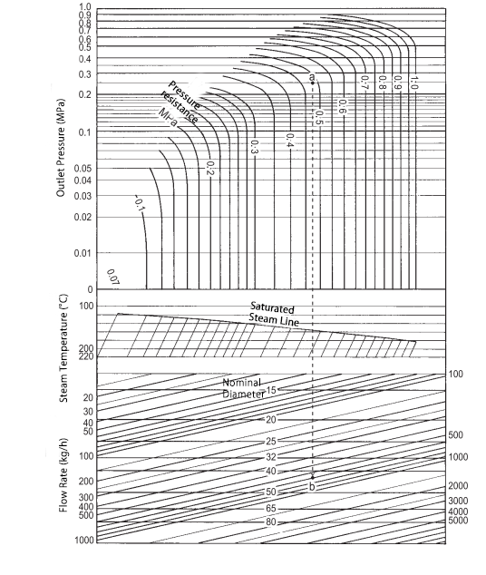
Nominal Diameter Selection
Please select the appropriate nominal diameter using the nominal diameter selection chart.
If the selected diameter is too small, the required flow rate may not be achieved.
If it is too large, issues such as hunting or instability may occur, leading to poor performance.
When the set pressure and outlet pressure remain constant within a certain range,
choose a nominal diameter where the difference between the minimum possible set differential pressure and the outlet pressure allows for stable operation.
Additionally, the minimum required flow rate should not be less than 50% of the selected nominal diameter’s rated flow rate (maximum flow rate at maximum differential pressure).
Example of Use:
Saturated Steam
- Set Pressure: 0.48 MPa
- Outlet Pressure: 0.25 MPa
- Flow Rate: 700 kg/h
To determine the appropriate nominal diameter:
- Locate the intersection of 0.48 MPa set pressure and 0.25 MPa outlet pressure on the selection chart.
- Identify the intersection with the 700 kg/h flow rate line.
- If the intersection falls between nominal diameters 40 and 50, select the larger diameter for stable operation.
- Therefore, the appropriate selection is nominal diameter 50.
Remarks:
For superheated steam, refer to the selection chart usage example on page 8.
Disassembly & Maintenance Space Required
| Nominal Diameter (mm) | 15 | 20 | 25 | 32 | 40 | 50 | 65 | 80 |
|---|---|---|---|---|---|---|---|---|
| Distance from Pipe Center Downward (mm) | 200 | 200 | 200 | 200 | 220 | 250 | 270 | 300 |
Piping Example
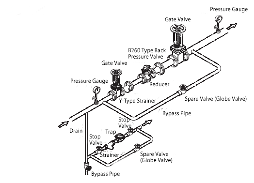
- Install it upright on a horizontal pipeline.
- When the outlet side is open to the atmosphere, the part indicated by the dashed line is not required