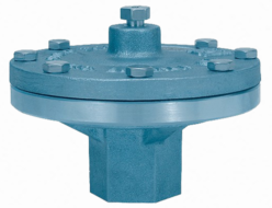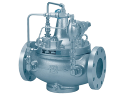
- This is an automatic straight-type back pressure valve designed for low-pressure gas applications.
- Suitable for high flow rates (nominal diameter 65–150).
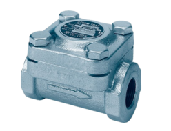
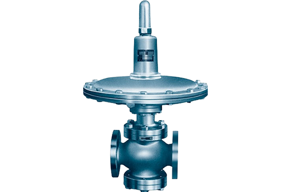
- For low flow rates (nominal diameter 15–50), please use the RLG61-2 type back pressure valve or RMD31L type back pressure valve.
Specifications and Materials
| Fluid | Nominal Diameter | Set Pressure Range (kPa) | Temperature (°C) | Main Component Materials | Pipe Connection | ||
| Valve Body | Valve Element / Seat | Diaphragm | |||||
| Air and Other Non-Corrosive Gases | 65–150 | 1.0–50 (¹) | 0–80 | Cast Iron | Stainless Steel | Synthetic Rubber | Flange JIS 10K Full-Face |
Note (1) A single spring cannot cover the entire range. Please refer to the “Primary Side Set Pressure Range (Spring Section)” and “Top Work Type (Model)” below.
Additionally, details on the types (models) of top work can be found on a separate page.
Remarks The valve box can also be manufactured from forged carbon steel or stainless steel. In this case, ASME Class 150 is also available.
Primary side set pressure range (spring section) and top work type (model)
| Nominal Diameter/ Set Pressure Range (kPa) | 1.0–1.5 kPa | 1.5–2.0 kPa | 2.0–3.0 kPa | 3.0–5.0 kPa | 5.0–7.0 kPa | 7.0–10 kPa | 10–15 kPa | 15–20 kPa | 20–30 kPa | 30–50 kPa |
|---|---|---|---|---|---|---|---|---|---|---|
| 65 | A | B | C | D | D | E | E | E | E | E |
| 80 | A | B | C | D | D | E | E | E | E | E |
| 100 | A | B | C | D | D | E | E | E | E | E |
| 125 | A | B | B | C | D | D | E | E | E | E |
| 150 | A | B | B | C | C | D | D | E | E | E |
Performance
| Offset | ≤12% of the maximum set pressure |
|---|---|
| Shut-off pressure drop | ≤15% of the maximum set pressure |
| Minimum adjustable flow rate | 5% of the rated flow rate |
| Valve seat leakage | ≤0.5% of the rated flow rate |
Cv Value
| Nominal Diameter | 65 | 80 | 100 | 125 | 150 |
|---|---|---|---|---|---|
| Cv | 35 | 46 | 72 | 123 | 178 |
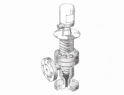
Structure and Dimensions
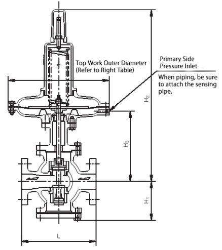
Dimensions and Weight
| Nominal Diameter | 65 | 80 | 100 | 125 | 150 |
|---|---|---|---|---|---|
| L (mm) | 240 | 270 | 310 | 360 | 380 |
| H₁ (mm) | 141 | 146 | 173 | 203 | 222 |
| H₂ (mm) | 590 | 602 | 630 | 675 | 694 |
| H₃ (mm) | 248 | 260 | 288 | 333 | 352 |
| Weight (kg) | 57 | 65 | 81 | 104 | 122 |
Note (3): The weight is for the case of Top Work C.
Top Work Outer Diameter Dimensions
| Model | A | B | C | D | E |
|---|---|---|---|---|---|
| Outer Diameter (mm) | 610 | 500 | 410 | 340 | 290 |
| Weight Adjustment (kg) | +27 | +12 | 0 | -7 | -10 |
Note (4): If the top work is other than type C, adjust the weight in the previous table by adding or subtracting the corresponding value.
Piping Example
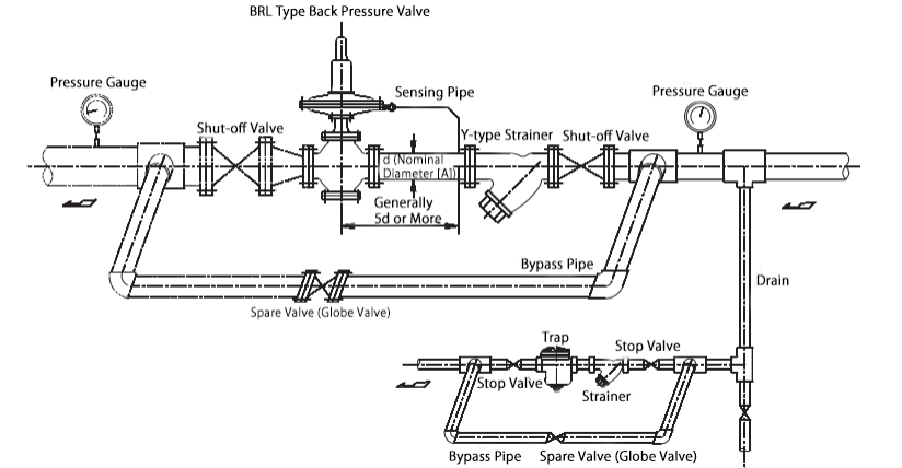
- Please install it upright on a horizontal pipe.
- If the fluid is air or similar and the outlet side is open to the atmosphere, the section with the two-dot chain line is not required.