Fushiman Co.
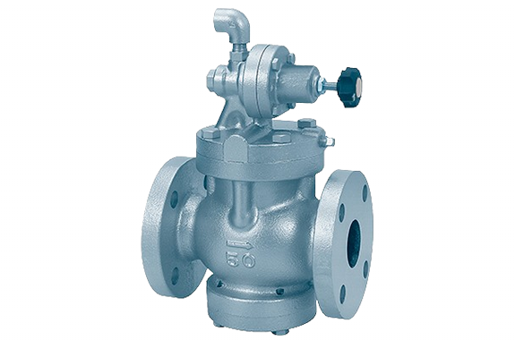
Fushiman BW5 type pressure reducing temperature control valve
Manufacturer: Fushiman Co.,LTD.
Model: BW5
| Model | Nominal diameter | Inlet Pressure | Set pressure | Temperature setting | Body Material | Connection |
|---|---|---|---|---|---|---|
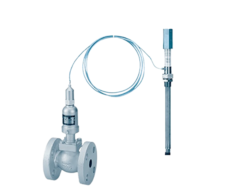
| The photo shows the BW5 main valve. | 15–150 | Max. 1.0 MPa | 0.03 to 0.9 MPa | 10 to 110°C | FC | Flange (screw-in temperature sensor) |
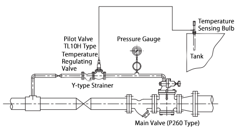
The BW5 model consists of a P260 type pressure reducing main valve, a TL10H type temperature regulating pilot valve, and a Y-type strainer.
| Application | For Heating | |||||||||||
| Set Temperature Range | 15 to 120°C (For details, refer to the next page) | |||||||||||
| Nominal Diameter | 15 | 20 | 25 | 32 | 40 | 50 | 65 | 80 | 100 | 125 | 150 | |
| Valve Type | Main Valve | Pilot-operated, Single Seat | ||||||||||
| Pilot Valve | TL10H type (single seat), nominal diameter 15 | |||||||||||
| Valve Seat Leakage | Less than 0.1% of the main valve rated flow | |||||||||||
| Operating Pressure (MPa) | Main Valve Inlet Side | 0.1 to 1.0 MPa | ||||||||||
| Main Valve Outlet Side | 0.03–0.2, 0.1–0.8, 0.5–0.9 MPa | |||||||||||
| Pipe Connection (Main Valve) | JIS 10K full-face flange | |||||||||||
| Fluid Through Valve | Steam (220°C or below) | |||||||||||
| Heated Fluid | Liquid | |||||||||||
| Applicable Pressure for Thermal Bulb (MPa) | 1.0 | |||||||||||
| Thermal Bulb Connection Standard | JIS Taper Pipe Thread | |||||||||||
| Capillary Tube Length | Standard length: 3 m (up to 5 m maximum) | |||||||||||
Note (1): When using the BW5 temperature regulating valve, the steam pressure must satisfy the following conditions:
(a) The secondary pressure must be 90% or less of the primary pressure and at least 0.03 MPa.
(b) The pressure reduction ratio between the primary and secondary pressures must be 20:1 or lower.
(c) The difference between the primary and secondary pressures must be at least 0.07 MPa.
Main Component Materials of the Main Valve (Pressure Reducing Valve)
| Part Name | Material |
|---|---|
| Valve Body & Cover | Cast Iron (*2) |
| Valve Plug & Seat | Stainless Steel |
| Piston & Cylinder | Stainless Steel |
Note (*2): For nominal diameters 15–40, the valve body is made of ductile cast iron.
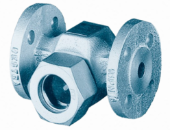
Materials of the Strainer for Pilot Valve
| Part Name | Material |
|---|---|
| Body | Ductile Cast Iron |
| Cover | Forged Brass |
| Screen | Perforated Stainless Steel Plate |
●For the materials of the pilot valve (TL10H type), please refer to page 150.
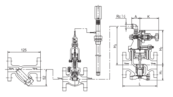
Main Valve Dimensions and Weight
| Item | 15A | 20A | 25A | 32A | 40A | 50A | 65A | 80A | 100A | 125A | 150A |
|---|---|---|---|---|---|---|---|---|---|---|---|
| L | 145 | 150 | 160 | 175 | 190 | 210 | 235 | 265 | 310 | 360 | 400 |
| H₁ | 81 | 76 | 74 | 79 | 85 | 95 | 112 | 123 | 150 | 174 | 202 |
| H₂ | 171 | 176 | 178 | 188 | 198 | 212 | 231 | 248 | 305 | 337 | 367 |
| H₃ | 196 | 201 | 203 | 213 | 223 | 237 | 256 | 273 | 320 | 352 | 382 |
| K | 115 | 115 | 115 | 111 | 111 | 111 | 111 | 111 | 162 | 162 | 162 |
| A | 46 | 46 | 46 | 45 | 50 | 50 | 50 | 50 | 58 | 58 | 58 |
| Weight (kg) | 8 | 8.5 | 10 | 12 | 14 | 18 | 26 | 32 | 51 | 71 | 105 |
Note: For the dimensions of the pilot valve (TL10H type) and the thermal bulb, please refer to page 150.
Standard Set Temperature Ranges
| Type | Set Temperature Range | Temperature Resistance |
|---|---|---|
| Low Temp Use | 10°C or higher to 70°C max | Set temperature +10°C |
| Standard Use | 50°C or higher to 110°C max | Set temperature +15°C (*3) |
Note (*3): The upper limit temperature is 120°C.
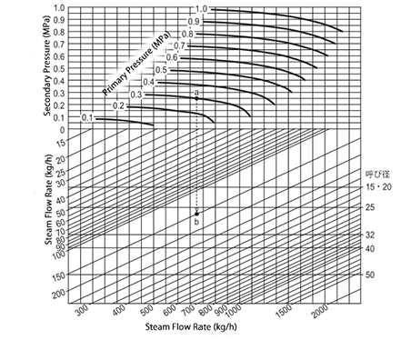
Nominal Diameter Selection Chart
(Example) Specifications:
Primary Pressure: 0.5 MPa
Set Pressure: 0.25 MPa
Saturated Steam: 700 kg/h
First, draw a vertical line downward from the intersection of the primary pressure (0.5 MPa) and the set pressure (0.25 MPa), and find the point where it intersects with the 700 kg/h flow rate line. This point falls between nominal diameters 40 and 50.
In this case, the larger size — nominal diameter 50 — is appropriate.
Related Products

REQUEST QUOTATION

PAYMENT

LINK


