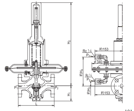
Dimensions
| Nominal Diameter | L | H₁ | H₂ | H₃ | H₄ | Weight (kg) |
|---|---|---|---|---|---|---|
| 20 | 185 | 81 | 448 | 25 | 152 | 18.5 |
| 25 | 196 | 84 | 452 | 30 | 156 | 20 |
| 32 | 233 | 92 | 475 | 53 | 179 | 23 |
| 40 | 233 | 92 | 475 | 53 | 179 | 24 |
| 50 | 237 | 92 | 475 | 53 | 179 | 25 |
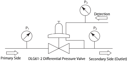
Installation Example
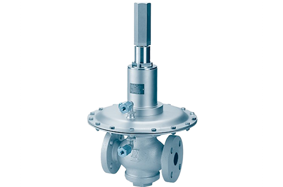
Manufacturer: Fushiman Co.,LTD.
Model: DLG61-2
| Model | Nominal diameter | Primary pressure measurement | Differential pressure setting range | Maximum operating temperature | Body Material | Connection |
|---|---|---|---|---|---|---|
| DLG61-2 | 20–50 | MAX. 400kPa | 0.5 to 8 kPa | 80℃ | FC | Flanges |
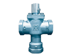
The DLG61-2 differential pressure valve is used in gas combustion lines and similar applications.
The main valve used as the base is the PLG61-2 pressure reducing valve. For detailed specifications of the main valve, please refer to the PLG61-2 pressure reducing valve (page 35 and beyond).
| Nominal Diameter | 20 | 25 | 32 | 40 | 50 | ||
| Main Flow Medium | Air and other non-corrosive gases | ||||||
| Pilot Flow Medium | Air and other non-corrosive gases | ||||||
| Primary Side | Maximum Pressure P₁ | 400kPa | |||||
| Maximum Temperature | 80℃ | ||||||
| Secondary Pressure P₂ | ≤ 20kPa | ||||||
| Pilot Pressure P₃ | ≤ 14kPa | ||||||
| Set Pressure Differential Range △P (P₂ – P₃) | 0.5〜1.4、1.2〜3.3、3.0〜8.0kPa | ||||||
| Main Valve Performance (1) | Cv Value (3) | 1.8 | 2.6 | 3.9 | 8.3 | 13 | |
| Minimum Differential Pressure (P₁ – P₂) | 2.0kPa | ||||||
| Offset (d) | Within 15% of the set pressure (minimum value 0.3 kPa) | ||||||
| Shut-off Pressure Increase | ≤ 0.4 kPa (for nominal diameters 20, 25), ≤ 1.5 kPa (for nominal diameters 32–50) | ||||||
| Minimum Adjustable Flow Rate | Nominal diameters 20, 25: 0.2–2 m³/h (standard condition), Nominal diameters 32–50: 5–10 m³/h (standard condition) | ||||||
| Valve Seat Leakage | ≤ 0.01% of the rated flow rate | ||||||
| Main Component Materials | Valve Body | Cast Iron | |||||
| Diaphragm Chamber Body | Rolled Steel | ||||||
| Spring Retainer Tube | Carbon Copper Tube | ||||||
| Valve Seat | Stainless Steel | ||||||
| Valve & Diaphragm | Synthetic Rubber | ||||||
| Main Valve Connection | Flange Type JIS 10K Full-Face | ||||||
| Nominal Diameter | L | H₁ | H₂ | H₃ | H₄ | Weight (kg) |
|---|---|---|---|---|---|---|
| 20 | 185 | 81 | 448 | 25 | 152 | 18.5 |
| 25 | 196 | 84 | 452 | 30 | 156 | 20 |
| 32 | 233 | 92 | 475 | 53 | 179 | 23 |
| 40 | 233 | 92 | 475 | 53 | 179 | 24 |
| 50 | 237 | 92 | 475 | 53 | 179 | 25 |


Copyright © Kouei Japan Trading | Get Quotation

