Manufacturer: Fushiman Co.,LTD.
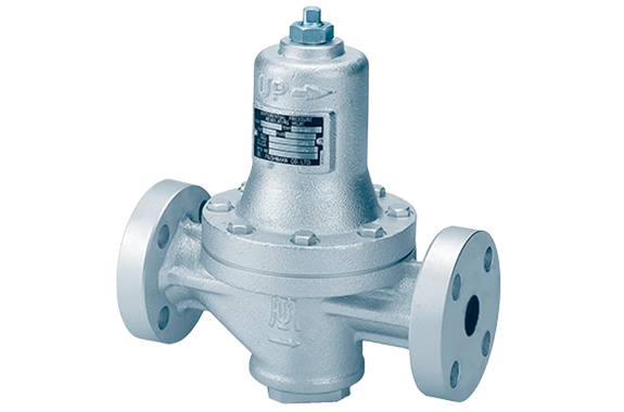
Model: DPD41B-2
| Model | Nominal diameter | Primary pressure measurement | Differential pressure setting range | Maximum operating temperature | Body Material | Connection |
|---|
| DPD41B-2 | 15〜25 | Max. 1.0 MPa | 0.03 to 0.15 MPa | 80℃ | CAC,FCD | Screw-in flange |
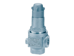
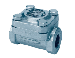
The DPD41B-2 and DPD41L-2 differential pressure valves are used in gas combustion lines, among other applications.
The main valve used as a base is the PPD41B-3 or PPD41L-3 pressure reducing valve.
For detailed specifications of the main valve, please refer to the PPD41B-3 pressure reducing valve (page 24 and beyond) or the PPD41L-3 pressure reducing valve (page 29).
Specifications and Performance
| Model | DPD41B-2 | DPD41L-2 |
| Application | Medium Pressure, Small Flow Rate | Low Pressure, Small Flow Rate |
| Nominal Diameter | 15 | 20 | 25 | 15 | 20 | 25 |
| Main Flow Medium | Non-corrosive gas |
| Pilot Flow Medium | Non-corrosive gas |
| Primary Side | Maximum Pressure P₁ | 1.0MPa | 0.3MPa |
| Maximum Temperature | 80֯C | 60֯C |
| Secondary Pressure P₂ | 0.03〜0.2、0.1〜0.75MPa | 0.02 〜0.14MPa |
| Pilot Pressure P₃ | ≤ 0.6MPa | ≤ 0.12MPa |
| Set Pressure Differential Range △P (P₂ – P₃) | 0.03 〜0.15MPa | 0.01〜0.02MPa |
| Main Valve Performance (1) | Cv Value (3) | 1.8 | 2.6 | 3.9 | 1.8 | 1.8 | 1.8 |
| Minimum Differential Pressure (P₁ – P₂) | 0.02MPa | 0.02MPa |
| Offset (d) | Within 10% of the set pressure | About 10% of the maximum set pressure |
| Shut-off Pressure Increase | ≤ 0.02MPa | About 5% of the maximum set pressure |
| Minimum Adjustable Flow Rate | 1 m³/h (standard condition) | Approximately 0.3 m³/h (standard condition) |
| Valve Seat Leakage | ≤ 0.01% of the rated flow rate | ≤ 0.01% of the rated flow rate |
| Main Component Materials | Valve Body | Bronze or Spheroidal Graphite Cast Iron | Spheroidal Graphite Cast Iron |
| Spring Retainer Tube | Bronze |
| Valve & Valve Seat | Stainless Steel Mesh (Valve Contact Surface: Synthetic Rubber) |
| Diaphragm | Synthetic Rubber |
| Main Valve Connection | Threaded Type JIS Rc or Flange Type JIS 10K Full-Face |
Note:
- The main valve performance values are based on the condition where the pilot output pressure (P₃) is 0 kPa (atmospheric pressure).
- The Cv values and maximum flow rates are the same as those for the PPD41B-3 pressure reducing valve (page 24) or the PPD41L-3 pressure reducing valve (page 29). Please refer to them for details.
- The offset, shut-off pressure increase, and minimum adjustable flow rate are reference values (nominal values).
Remarks:
- The above specifications are for reference only. We will review them individually according to your usage conditions.
Structure and Dimensions
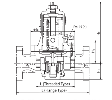
Note (4):
The pilot output pressure (P₃) hole is positioned at a right angle on the right side when viewed from the downstream side.
This diagram shows the DPD41B-2 model (the DPD41L-2 model differs slightly).
Dimensions
| Model | Valve Body Material & Pipe Connection | Nominal Diameter | L | H₁ | H₂ | H₃ | E | Weight (kg) |
|---|
| DPD41B-2 | Bronze (Threaded Type) | 15 | 80 | 43 | 133 | 68 | 100 | 2.8 |
| 20 | 115 | 47 | 180 | 80 | 130 | 5.5 |
| 25 | 170 | 47 | 180 | 80 | 130 | 5.5 |
| Spheroidal Graphite Cast Iron (Flange Type) | 15 | 95 | 43 | 133 | 68 | 100 | 4.6 |
| 20 | 130 | 47 | 180 | 80 | 130 | 7.9 |
| 25 | 215 | 55 | 170 | 130 | 130 | 10.9 |
| DPD41L-2 | Threaded Type / Spheroidal Graphite Cast Iron | 15 | 95 | 43 | 133 | 68 | 100 | 3.0 |
| 20 | 130 | 47 | 180 | 80 | 130 | 5.8 |
| 25 | 130 | 47 | 180 | 80 | 130 | 5.8 |
| Spheroidal Graphite Cast Iron (Flange Type) | 15 | 95 | 43 | 133 | 68 | 100 | 4.6 |
| 20 | 130 | 47 | 180 | 80 | 130 | 7.9 |
| 25 | 215 | 55 | 170 | 130 | 130 | 8.9 |
Installation Example
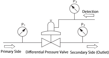
The nominal diameter selection and piping examples for the DPD41B-2 and DPD41L-2 differential pressure valves are the same as those for the PPD41B-3 pressure reducing valve (pages 24, 25) and the PPD41L-3 pressure reducing valve (page 29). Please refer to them.