Fushiman Co.
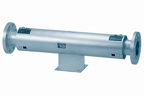
Fushiman JOB31T type expansion joint (double type)
Manufacturer: Fushiman Co.,LTD.
Model: JOB31T
| Model | Nominal diameter | Method | Fluid | Maximum Operating Pressure | Maximum Operating Temperature | Body Material | Connection |
|---|---|---|---|---|---|---|---|
| JOB31T | 20–500 | Bellows | Steam Gas Liquid | 1.0 MPa | 220°C | SS | Flanges |
Application
For absorbing expansion and contraction in piping.
Quality
Compliant with JIS B 2352 standard
Specifications
| Nominal Diameter | 20–500 |
| Maximum Operating Pressure | 1.0 MPa |
| Pressure Test | 1.5 MPa |
| Maximum Operating Temperature | 220°C |
| Fluid | Steam, hot/cold water, oil, and non-corrosive gases |
| Pipe Connection | Flange JIS 10K |
Features
- Complies with JIS B 2352 — Designed according to JIS B 2352-2013 Appendix JD (Reference) “Product specification example of bellows-type expansion joints (Application A)”.
- Bellows are made of low-carbon SUS316L — Prevents carbon precipitation from welding and provides excellent durability against intergranular corrosion and pitting.
- All wetted parts are stainless steel — Safe for clean or chemical fluids without concern.
- No packing is used — Completely leak-free.
- Inner pipe is SUS316L — Prevents pressure loss and flow-induced vibration, improving durability.
Caution for Use
Do not use the expansion joint in a state that exceeds the maximum or minimum face-to-face dimensions. If the specified face-to-face dimension is exceeded, please inspect and correct the fixings, guides, etc.
For the duplex type, the anchor base of the product is also fixed in the middle.
Structure / Part Name / Material
| Part Name | Material | Part Name | Material |
|---|---|---|---|
| Tension Flange | SUS316L | Inner Tube | SUS316L |
| Pipe Flange | SS400 | Face-to-Face Fixing Bolt | SS400 |
| Outer Tube | SPHC or SS400 | Face-to-Face Fixing Plate (20–250A) | SS400 |
| Bellows | SUS316L | Reinforcement Ring (300–500A) | SS400 |
| Part Name | Material | Part Name | Material |
|---|---|---|---|
| Tension Flange | SUS316L | Face-to-Face Fixing Bolt | SS400 |
| Pipe Flange | SS400 | Face-to-Face Fixing Plate (20–250A) | SPHC or SS400 |
| Outer Tube | SPHC or SS400 | Reinforcement Ring (300–500A) | SS400 |
| Bellows | SUS316L | Anchor Base | SS400 |
| Inner Tube | SUS316L |
Dimensions / Performance / Mass
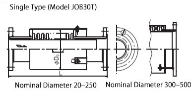
Single Type: JOB30T Model
| Part/Nominal Diameter | 20 | 25 | 32 | 40 | 50 | 65 | 80 | 100 | 125 | 150 | 200 | 250 | 300 | 350 | 400 | 450 | 500 |
|---|---|---|---|---|---|---|---|---|---|---|---|---|---|---|---|---|---|
| Set Face-to-Face Length (L) | 365 | 415 | 440 | 465 | 490 | ||||||||||||
| Maximum Face-to-Face (L₁) | 375 | 425 | 450 | 475 | 500 | ||||||||||||
| Minimum Face-to-Face (L₂) | 340 | 390 | 415 | 440 | 465 | ||||||||||||
| Max. Stroke (δ) | Stretch: 10 / Shrink: 25 (※) | ||||||||||||||||
| Outer Diameter (D₀) | 58 | 73 | 98 | 110 | 136 | 162 | 212 | 235 | 292 | 333 | 387 | 422 | 470 | 517 | 567 | ||
| Mass (kg) | 3.5 | 4.5 | 5.5 | 6 | 7.5 | 11 | 12 | 16 | 21 | 27 | 36 | 52 | 111 | 130 | 160 | 186 | 208 |
Note (※1):
Shrink amount δc = 35 mm is also available (Model JOB24L, nominal diameter 20–200. Not a JIS standard product).
Supplement 1:
The value δ is the difference between the maximum and minimum face-to-face lengths. We use this method especially when high precision is not required.
Supplement 2:
After hydraulic pressure testing, be sure to remove both the face-to-face fixing bolts and plates for nominal diameters 20–250, and the fixing bolts for nominal diameters 300–500.
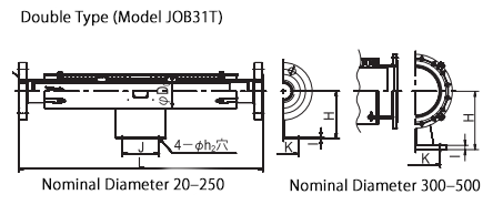
Double Type: JOB31T Model
| Part/Nominal Diameter | 20 | 25 | 32 | 40 | 50 | 65 | 80 | 100 | 125 | 150 | 200 | 250 | 300 | 350 | 400 | 450 | 500 | |
| Set Face-to-Face Length (L) | 680 | 780 | 880 | 930 | 980 | 1030 | 1080 | |||||||||||
| Maximum Face-to-Face (L₁) | 700 | 800 | 900 | 950 | 1000 | 1050 | 1100 | |||||||||||
| Minimum Face-to-Face (L₂) | 630 | 730 | 830 | 880 | 930 | 980 | 1030 | |||||||||||
| Max. Stroke (δ) | Extension (δe): 20 (10 per side) Compression (δc): 50 (25 per side) (※2) | |||||||||||||||||
| Anchor base | K | 60 | 70 | 80 | 100 | 110 | 130 | 150 | 180 | 220 | 280 | 300 | 350 | 400 | 450 | 500 | |||
| J | 100 | 120 | 160 | 180 | 200 | 250 | 300 | 350 | 400 | |||||||||
| H | 100 | 120 | 130 | 140 | 150 | 170 | 200 | 220 | 250 | 300 | 350 | 450 | 500 | 550 | 600 | |||
| I | 3.2 | 4.0 | 4.5 | 25 | ||||||||||||||
| Bolt Hole Diameter – h₂ | 12 | 15 | 19 | 23 | 25 | 27 | 33 | 39 | ||||||||||
| Bolt Thread Nominal Size | M10 | M12 | M16 | M20 | M22 | M24 | M30 | M36 | ||||||||||
| Outer Diameter (D₀) | 58 | 73 | 98 | 110 | 136 | 162 | 212 | 235 | 292 | 333 | 387 | 422 | 470 | 517 | 567 | |||
| Mass (kg) | 5 | 6 | 8 | 8.5 | 11 | 14 | 17 | 22 | 35 | 46 | 66 | 96 | 225 | 271 | 325 | 390 | 442 | |
Note (※2):
Compression δc: 70 mm (35 mm per side) is also available (Model JOB43L, nominal diameter 20–250. This is not a JIS standard product).
Supplement 1:
The value δ is calculated by subtracting the minimum face-to-face length from the maximum. This method is used especially when no strict dimensional specification is required.
Supplement 2:
After the hydraulic pressure test, be sure to remove both the fixing bolts and plates for nominal diameters 20–250, and the fixing bolts for diameters 300–500.
Related Products
REQUEST QUOTATION

PAYMENT

LINK


