Fushiman Co.
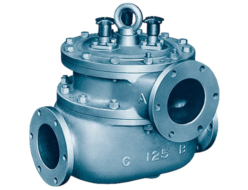
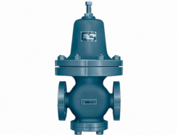
Fushiman P260-DHC Pressure Reducing Valves
Manufacturer: Fushiman Co.,LTD.
Model: P260-DHC
| Model | Nominal Diameter (mm) | Primary Side Pressure | Secondary Side Set Range | Maximum Operating Temperature | Body Material | Connection |
|---|---|---|---|---|---|---|
| P260-DHC | 15〜250 | MAX. 1.0MPa | 0.03~0.9MPa | 220℃ | FC,FCD,SCPH | Flange |
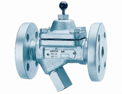
The DHC-type pressure reducing valve is designed for steam pressure reduction in energy plants and receiving equipment, featuring a secondary pressure balance structure.
- Even if the primary side pressure fluctuates, the presence of a check valve or control valve and a high or low flow meter on the primary side of the pressure reducing valve ensures stable pressure control.
- It is also suitable for use as a second-stage pressure reducing valve in two-stage pressure reduction systems, where the pressure reducing valve is used in series.
Specifications and Performance
| Nominal Diameter | 15–250 mm | ||
|---|---|---|---|
| Fluid | Steam | ||
| Primary Side (Steam) | Pressure | 0.1–1.0 MPa | |
| Maximum Temperature | 220°C | ||
| Secondary Side Set Pressure Range | 0.03–0.2 MPa, 0.1–0.8 MPa, 0.5–0.9 MPa | ||
| Cv Value | 4.5d²–3.1d² | ||
| Maximum Pressure Reduction Ratio | 20:1 | ||
| Minimum Differential Pressure Setting | 10% of primary side pressure (minimum 0.07 MPa) | ||
| Offset | 0.03 MPa or less | ||
| Shutoff Pressure Rise | 0.02 MPa or less | ||
| Minimum Adjustable Flow Rate | 5% of rated flow | ||
| Valve Seat Leakage | 0.05% or less of rated flow | ||
| Main Component Materials | Valve Body | Cast iron (1) or cast steel | |
| Main Valve & Valve Seat | Stainless steel | ||
| Piston & Cylinder | Stainless steel | ||
| Diaphragm | Stainless steel | ||
| Balance Piston | Stainless steel | ||
| Pipe Connection | JIS10K full-face seating | ||
Note (1): The valve body for nominal diameters 15 to 40 is made of spheroidal graphite cast iron (ductile iron).
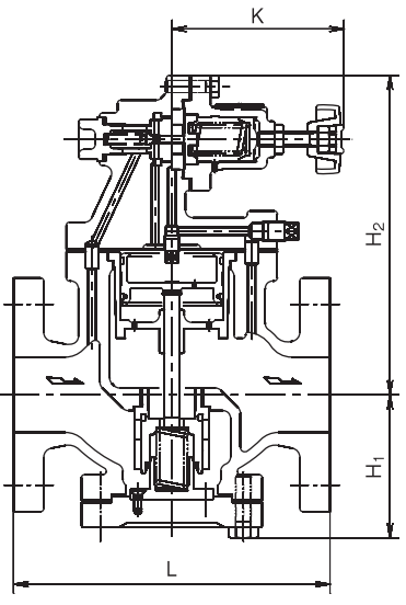
Structure
Notes:
- For dimensions and weight.
- For nominal diameter selection.
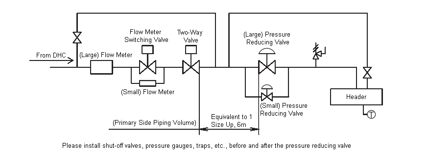
DHC (District Heating and Cooling) System – Example of P260-DHC Pressure Reducing Valve Piping
Parent-Child Valve System
Since the primary-side pressure of the pressure reducing valve will not stabilize when restricted by check valves or flow meters, use a parent-child valve system that arranges large (大) and small (小) pressure reducing valves in parallel.- The nominal diameter of the small (小) pressure reducing valve should be selected so that it can handle a flow rate greater than the maximum flow of the small flow meter.
- The setting pressure of the large (大) pressure reducing valve should be set 0.03 MPa lower than that of the small (小) pressure reducing valve.
Piping Volume on the Primary Side of the Pressure Reducing Valve
- As much as possible, increase the primary-side piping volume by using a pipe one size larger than the pressure reducing valve, ensuring a length equivalent to 6 meters.
- If a check valve or flow meter is installed upstream, ensure that there is adequate piping volume from the small (小) flow meter.
Related Products
REQUEST QUOTATION

PAYMENT

LINK


