- Home
- Products
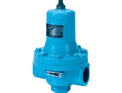
- Fushiman P260 Pressure Reducing Valves (Valve Box Stainless Steel Casting: Oil-Prohibited Finish)
Fushiman Co.
Fushiman P260 Pressure Reducing Valves (Valve Box Stainless Steel Casting: Oil-Prohibited Finish)
Manufacturer: Fushiman Co.,LTD.
Model: P260
| Model | Nominal Diameter (mm) | Primary Side Pressure | Secondary Side Set Range | Maximum Operating Temperature | Body Material | Connection |
|---|---|---|---|---|---|---|
| P260 | 15〜250 | MAX. 3.0MPa | 0.03~2.5MPa | 300°C | FC,FCD,SCPH,SCS | Flange |
● The nominal diameter ranges widely from 15 to 250.
● Stable operation is ensured even under high or low differential pressure.
● All performance values are based on experimental data.
● If the primary pressure on the inlet side of the pressure-reducing valve fluctuates due to being controlled by a check valve or flow control valve, or if the pressure-reducing valve is used in series in a two-stage pressure reduction system, please use the P260-DHC model (page 10) for the second stage.
Specifications and Materials
| Fluid | Pressure (MPa) | Maximum Operating Tempera-ture (°C) | Detection Method | Main Component Materials | Pipe Connec-tion | |||||
|---|---|---|---|---|---|---|---|---|---|---|
| Primary Side | Secondary Side Setting Range | Valve Box | Main Valve Body & Seat | Piston & Cylinder | Pilot Valve Body & Seat | Diaph-ragm | ||||
| Steam | 0.1 – 1.0 | 0.03 – 0.2 0.1 – 0.8 0.5 – 0.9 | 220 | Internal or External | Cast Iron | Stainless Steel | Stainless Steel | Stainless Steel | Stainless Steel | Flange JIS 10K Full Face |
| 0.1 – 1.6 | 0.03 – 0.2 0.1 – 0.8 0.5 – 1.44 | 220 | Cast Iron | Stainless Steel | Stainless Steel | Stainless Steel | Stainless Steel | Flange JIS 16K Full Face | ||
| 0.1 – 2.0 | 0.03 – 0.2 0.1 – 0.8 0.5 – 1.6 | 220 | Ductile Cast Iron | Stainless Steel | Stainless Steel | Stainless Steel | Stainless Steel | Flange JIS 20K Flat Face | ||
| 0.1 – 1.0 | 0.03 – 0.2 0.1 – 0.8 0.5 – 0.9 | 260 | Cast Steel | Stainless Steel | Stainless Steel | Stainless Steel | Stainless Steel | Flange JIS 10K Flat Face | ||
| 300 | ||||||||||
| 0.1 – 1.6 | 0.03 – 0.2 0.1 – 0.8 0.5 – 1.44 | 260 | Cast Steel | Stainless Steel | Stainless Steel | Stainless Steel | Stainless Steel | Flange JIS 16K Flat Face | ||
| 300 | ||||||||||
| 0.1 – 2.0 | 0.03 – 0.2 0.1 – 0.8 0.5 – 1.6(2) | 260 | Cast Steel | Stainless Steel | Stainless Steel | Stainless Steel | Stainless Steel | Flange JIS 20K Flat Face | ||
| 300 | ||||||||||
| 0.2 – 3.0 | 0.1 – 0.8 0.5 – 1.6 1.0 – 2.5 | 240 | Cast Steel | Stainless Steel + Stellite Weld Overlay | Stainless Steel | Stainless Steel + Stellite Weld Overlay | Stainless Steel | Flange JIS 30K Flat Face | ||
| 0.1 – 1.0 | 0.03 – 0.2 0.1 – 0.8 0.5 – 0.9 | 184 | Stainless Steel Cast Steel | Stainless Steel | Stainless Steel | Stainless Steel | Stainless Steel | Flange JIS 10K Full Face | ||
Notes:
(1) Valve boxes with a nominal diameter of 15 to 40 are made of ductile cast iron.
(2) Manufactured up to 1.8 MPa.
(3) Optional. For installation areas of seismic piping, please refer to separate technical documents.
Remarks:
- For a nominal diameter of 200, the maximum primary pressure is 1.6 MPa. For a nominal diameter of 250, the maximum is 1.0 MPa.
- ASME Class 150 and 300 versions are also available.
Performance
| Maximum Pressure Reduction Ratio | 20 :1 | ||
|---|---|---|---|
| Minimum Set Differential Pressure | 10% of Primary Side Pressure (Minimum Value: 0.07 MPa) | ||
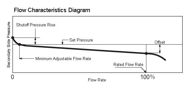
| Offset | Set Pressure Range (MPa) | 0.03 – 0.2, 0.1 – 0.8 | 0.03 MPa or less |
| 0.5 – 0.9 (1.44) (1.6) | 0.05 MPa or less | ||
| Shutoff Pressure Rise | Set Pressure Range (MPa) | 0.03 – 0.2, 0.1 – 0.8 | 0.02 MPa or less |
| 0.5 – 0.9 (1.44) (1.6) | 0.04 MPa or less | ||
| Minimum Adjustable Flow Rate | 5% of Rated Flow Rate | ||
| Valve Seat Leakage | 0.05% or less of Rated Flow Rate | ||
Structure and Dimensions
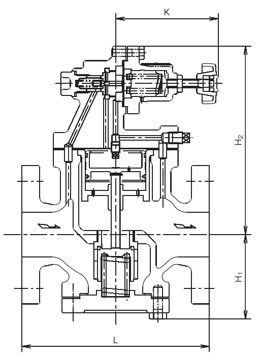
Notes:
- The diagram shows the state when the flow rate is zero (valve fully closed).
- The diagram represents an internal detection type.
- Handles are not included in cast bronze products.
- For nominal diameters of 200 and above, as well as for JIS 30K applications, some shapes may differ.
Dimensions
(mm)
| Valve Body Material | Nominal Diameter /Dimensions | 15 | 20 | 25 | 32 | 40 | 50 | 65 | 80 | 100 | 125 | 150 | 200 | 250 | |
|---|---|---|---|---|---|---|---|---|---|---|---|---|---|---|---|
| Cast Iron | L | JIS10K | 145 | 150 | 160 | 175 | 190 | 210 | 235 | 265 | 310 | 360 | 400 | 490 | 620 |
| JIS16K | 145 | 150 | 160 | 175 | 190 | 210 | 235 | 270 | 315 | 365 | 405 | 500 | — | ||
| H₁ | 78 | 73 | 71 | 77 | 85 | 95 | 112 | 123 | 150 | 174 | 202 | 248 | 300 | ||
| H₂ | 171 | 176 | 178 | 188 | 198 | 212 | 231 | 248 | 305 | 337 | 367 | 482 | 549 | ||
| K | 115 | 115 | 115 | 115 | 111 | 111 | 111 | 111 | 162 | 162 | 162 | 194 | 194 | ||
| Ductile Cast Iron | L | JIS20K | 149 | 154 | 164 | 179 | 194 | 206 | 231 | 266 | — | — | — | — | — |
| H₁ | 82 | 77 | 75 | 79 | 85 | 95 | 110 | 121 | — | — | — | — | — | ||
| H₂ | 171 | 176 | 178 | 188 | 198 | 212 | 231 | 248 | — | — | — | — | — | ||
| K | 115 | 115 | 115 | 115 | 111 | 111 | 111 | 111 | — | — | — | — | — | ||
| Cast Steel | L | JIS10K | 182 | 186 | 186 | 206 | 212 | 228 | 252 | 270 | 318 | 358 | 398 | 496 | 630 |
| JIS16K | 182 | 186 | 186 | 206 | 212 | 228 | 252 | 274 | 326 | 362 | 402 | 504 | 638 | ||
| JIS20K | 186 | 190 | 190 | 210 | 216 | 232 | 256 | 278 | 330 | 370 | 410 | 512 | 650 | ||
| JIS30K | 194 | 194 | 195 | 218 | 224 | 240 | 268 | 290 | — | — | — | —— | — | ||
| H₁ | 77 | 77 | 75 | 77 | 85 | 95 | 110 | 124 | 151 | 175 | 207 | 248 | 303 | ||
| H₂ | 177 | 177 | 179 | 189 | 199 | 213 | 232 | 249 | 305 | 337 | 367 | 482 | 552 | ||
| K | 107 | 107 | 107 | 107 | 103 | 103 | 103 | 103 | 147 | 147 | 147 | 194 | 194 | ||
| Stainless Steel / Cast Steel | L | JIS10K | 182 | 186 | 186 | 206 | 212 | 228 | 252 | 270 | 318 | 358 | 398 | —— | — |
| H₁ | 75 | 75 | 75 | 85 | 85 | 95 | 110 | 124 | 151 | 175 | 207 | —— | — | ||
| H₂ | 179 | 179 | 179 | 198 | 198 | 212 | 231 | 248 | 305 | 337 | 367 | — | — | ||
| K | 117 | 117 | 117 | 113 | 113 | 113 | 113 | 113 | 162 | 162 | 162 | —— | — | ||
Notes:
- K indicates the dimensions when the adjustment spring is free.
- H₁, H₂, and K values for JIS 30K may differ slightly.
Mass
(kg)
| Nominal Diameter | 15 | 20 | 25 | 32 | 40 | 50 | 65 | 80 | 100 | 125 | 150 | 200 | 250 |
|---|---|---|---|---|---|---|---|---|---|---|---|---|---|
| Cast Iron JIS10K | 8 | 8.5 | 10 | 12 | 14 | 18 | 26 | 32 | 51 | 71 | 105 | 195 | 315 |
| Ductile Cast Iron JIS20K | 9 | 9.5 | 11 | 13 | 15 | 19 | 27 | 35 | — | — | — | — | — |
| Cast Steel JIS20K | 10 | 11 | 13 | 14 | 17 | 22 | 30 | 39 | 60 | 92 | 131 | 228(4) | 341(5) |
| Cast Steel JIS30K | 12 | 13 | 15 | 16 | 20 | 24 | 35 | 43 | — | — | — | — | — |
| Stainless Steel Cast Steel JIS10K | 9 | 10 | 12 | 15 | 16 | 21 | 28 | 35 | 55 | 86 | 124 | — | — |
Notes:
- (4) Mass of JIS 16K
(5) Mass of JIS 10K
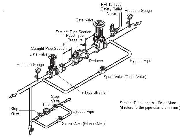
Piping Example
- Please install it vertically on a horizontal pipe.
- Maintenance space as shown in the table below is required for the pressure reducing valve.
Disassembly & Maintenance Required Space (mm)
| Nominal Diameter | 15 | 20 | 25 | 32 | 40 | 50 | 65 | 80 | 100 | 125 | 150 | 200 | 250 |
|---|---|---|---|---|---|---|---|---|---|---|---|---|---|
| Distance Below Pipe Center (mm) | 200 | 200 | 200 | 200 | 220 | 250 | 270 | 300 | 350 | 410 | 460 | 560 | 700 |
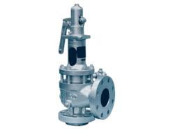
Nominal Diameter Selection for Alarm Safety Relief Valve
The table below shows the nominal diameter of the alarm safety relief valve used on the secondary side of a P260 type pressure reducing valve (for steam: 1.0 MPa, 220°C or below).
| P260 Type Pressure Reducing Valve Specifications | Safety Relief Valve Blowout Pressure (MPa) | P260 Type Pressure Reducing Valve – Nominal Diameter | ||||||||||||||
|---|---|---|---|---|---|---|---|---|---|---|---|---|---|---|---|---|
| Primary Side Pressure (MPa) | Set Pressure (MPa) | 15 | 20 | 25 | 32 | 40 | 50 | 65 | 80 | 100 | 125 | 150 | 200 | 250 | ||
| 0.3 or less | 0.03 | 0.08 | 15-20 | 15 | 20 | 15-20 | 15-20 | 15-20 | 25 | 32 | 40 | 40G65 65 | 40G65 65 | 40H80 80 | 50J80 | 80K100 |
| More than 0.3 and up to 0.6 or less | 0.03 | 0.08 | 15-20 | 15 | 20 | 15-20 | 15-20 | 25 | 32 | 40 | 50 | 40G65 65 | 40H80 80 | 50J80 | 80K100 | 80L100 |
| 0.6 or less | 0.05 | 0.1 | 15-20 | 15 | 20 | 15-20 | 15-20 | 25 | 32 | 40 | 50 | 40G65 65 | 40H80 | 50J80 | 80K100 | 80L100 |
| More than 0.6 and up to 1.0 or less | 0.05 | 0.1 | 15-20 | 15 | 20 | 15-20 | 15-20 | 25 | 40 | 50 | 65 | 40G65 80 | 40H80 | 50J80 | 80K100 | 80L100 |
| 0.7 or less | 0.1 | 0.15 | 15-20 | 15 | 20 | 15-20 | 15-20 | 25 | 32 | 40 | 50 | 40G65 65 | 40H80 80 | 50J80 | 80K100 | 80L100 |
| More than 0.7 and up to 1.0 or less | 0.1 | 0.15 | 15-20 | 15 | 20 | 15-20 | 25 | 32 | 40 | 50 | 65 | 40G65 80 | 40H80 | 50J80 | 80L100 | 100M150 |
| 0.7 or less | 0.2 | 0.28 | 15-20 | 15 | 20 | 15-20 | 15-20 | 15-20 | 25 | 32 | 40 | 40G65 65 | 40G65 65 | 40H80 80 | 50J80 | 80K100 |
| More than 0.7 and up to 1.0 or less | 0.2 | 0.28 | 15-20 | 15 | 20 | 15-20 | 15-20 | 25 | 32 | 40 | 50 | 40G65 65 | 40G65 80 | 40H80 | 50J80 | 80L100 |
| 0.9 or less | 0.3 | 0.38 | 15-20 | 15 | 20 | 15-20 | 15-20 | 15-20 | 25 | 32 | 40 | 40G65 65 | 40G65 65 | 40H80 80 | 50J80 | 80K100 |
| More than 0.9 and up to 1.0 or less | 0.3 | 0.38 | 15-20 | 15 | 20 | 15-20 | 15-20 | 15-20 | 32 | 32 | 40 | 40G65 65 | 40G65 80 | 40G80 80 | 50J80 | 80K100 |
| 1.0 or less | 0.4 | 0.48 | 15-20 | 15 | 20 | 15-20 | 15-20 | 15-20 | 25 | 32 | 40 | 40G65 50 | 40G65 65 | 40G65 80 | 50J80 | 80K100 |
| 1.0 or less | 0.5 | 0.6 | 15-20 | 15 | 20 | 15-20 | 15-20 | 15-20 | 25 | 32 | 40 | 25E50 50 | 40G65 65 | 40G65 80 | 40H80 | 50J80 |
| 1.0 or less | 0.6 | 0.7 | 15-20 | 15 | 20 | 15-20 | 15-20 | 15-20 | 15-20 | 25 | 32 | 25E50 40 | 40G65 65 | 40G65 65 | 40H80 | 50J80 |
| 1.0 or less | 0.7 | 0.82 | 15-20 | 15 | 20 | 15-20 | 15-20 | 15-20 | 15-20 | 25 | 32 | 25E50 40 | 25E50 50 | 40G65 65 | 40G65 80 | 40H80 |
| 1.0 or less | 0.8 | 0.92 | 15-20 | 15 | 20 | 15-20 | 15-20 | 15*20 | 15-20 | 15-20 | 25 | 25E50 32 | 25E50 40 | 40G65 50 | 40G65 80 | 40H80 |
Notes:
- The table shows the nominal diameter of the alarm safety relief valve for failures such as overpressure in the P260 type pressure reducing valve (for steam). It has no relation to legal regulations.
- For P260 type nominal diameters 15 to 80, the values indicate the nominal diameter of the RPF12 type safety relief valve. For P260 type nominal diameters 100 to 250, the upper row shows RPN6B type safety relief valve, and the lower row shows RPF12 type safety relief valve nominal diameters.
- If the set pressure of the P260 type pressure reducing valve (for steam) falls between two values in the table, choose the nominal diameter corresponding to the smaller set pressure.
- The relief capacity of the safety relief valve is approximately 5-10% of the rated flow of the reducing valve. The blowout pressure is indicated in the table below.
- If the set pressure is 0.5 MPa or higher, for 0.5 – 1.6 MPa (medium pressure) applications, add 0.02 MPa to the values in the table.
Alarm Safety Relief Valve Blowout Pressure
(MPa)
| Set Pressure of Pressure Reducing Valve | Blowout Pressure of Safety Relief Valve |
|---|---|
| 0.1 MPa or less | Set Pressure of Pressure Reducing Valve + 0.05 MPa or more |
| More than 0.1 MPa and up to 0.4 MPa | Set Pressure of Pressure Reducing Valve + 0.08 MPa or more |
| More than 0.4 MPa and up to 0.6 MPa | Set Pressure of Pressure Reducing Valve + 0.1 MPa or more |
| More than 0.6 MPa and up to 0.8 MPa | Set Pressure of Pressure Reducing Valve + 0.12 MPa or more |
| More than 0.8 MPa | Set Pressure of Pressure Reducing Valve + 15% |
5. If the primary side pressure of the pressure reducing valve exceeds 1.0 MPa, or if the steam temperature exceeds 220°C, the required blowout amount of the safety relief valve should be calculated accordingly.
Please refer to the blowout capacity tables for RPF12 type, RPF13 type, or RPN6B type saturated steam to determine the appropriate nominal diameter for the safety relief valve.
Related Products
REQUEST QUOTATION

PAYMENT

LINK


