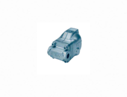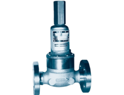
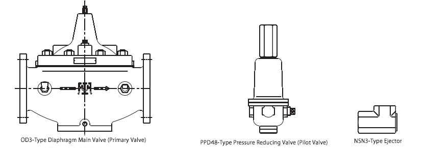
- This valve is a basic valve (main valve) that can be equipped with various pilot valves and accessories, making it one of the 42 series valves suitable for a wide range of applications.
- Since it is a pilot-operated type, it has a large capacity relative to its nominal diameter. Additionally, the offset is minimized.
- For registered certified products of automatic regulating valves for fire protection equipment, please refer to the separate listing (page 116).
Specifications and Materials
| Fluid | Pressure (MPa) | Temperature (°C) | Main Valve (OD3 Type) – Main Material Components | Pilot Valve (PPD48 Type) – Main Material Components | Piping Connection (Main Valve) | |||||
| Primary Side | Secondary Side Setting Range | Valve Body & Cover | Valve Element & Diaphragm | Valve Seat | Valve Body | Spring Protection Tube | Valve Element | |||
| Water, Light Oil, Other Non-Corrosive Liquids | 0.055~1.0 | 0.015~0.07 0.05~0.3 0.2~0.8 0.7~1.4 1.2~1.96 | 0~80 | Cast Iron (Epoxy & Resin Coating for Wetted Parts) | Synthetic Rubber | Bronze | Bronze | Cast Iron | Bronze or Stainless Steel with Synthetic Rubber Coating | Flange JIS 10K Full-Face |
| 0.055~1.6 | Flange JIS 16K Full-Face | |||||||||
| 0.055~2.0 | Cast Bronze | Flange JIS 20K Flat-Face | ||||||||
Notes:
- Valve bodies are also available in cast stainless steel.
- Valve bodies (cast iron) with nylon coating (for temperatures below 60°C) are also available.
Performance
| Maximum Pressure Reduction Ratio | 10:1 |
|---|---|
| Maximum Set Differential Pressure | 1.5 MPa |
| Minimum Set Differential Pressure | 0.04 MPa |
| Offset | Within 10% of the set pressure (minimum 0.04 MPa) |
| Maximum Usable Fluid Viscosity | Light oil, ≤ 20 mm²/s |
| Valve Seat Leakage | ≤ 0.01% of the rated flow |
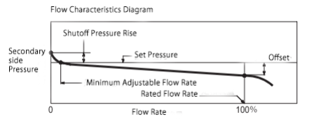
Shutoff Pressure Rise
| Set Pressure Range (MPa) | Shutoff Pressure Rise (MPa) |
|---|---|
| 0.015 ~ 0.07 | 0.01 ~ 0.03 |
| 0.05 ~ 0.3 | 0.02 ~ 0.05 |
| 0.2 ~ 0.8 | 0.04 ~ 0.08 |
| 0.7 ~ 1.4 | 0.06 ~ 0.1 |
| 1.2 ~ 1.96 | 0.08 ~ 0.12 |
Note: The higher the primary-side pressure for the same set pressure, the greater the shutoff pressure rise.
Minimum Adjustable Flow Rate
| Nominal Diameter | 40 | 50 | 65 | 80 | 100 | 125 | 150 | 200 | 250 | 300 |
|---|---|---|---|---|---|---|---|---|---|---|
| Minimum Adjustable Flow Rate (Water) (¹) | 10 | 10 | 10 | 10 | 75 | 100 | 135 | 200 | 335 | 500 |
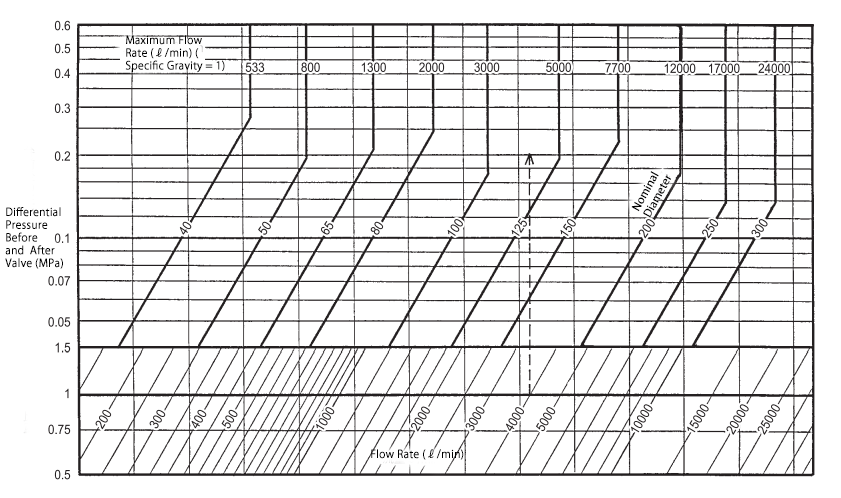
Nominal Diameter Selection
Select the appropriate nominal diameter using the nominal diameter selection diagram.
When the primary-side pressure and set pressure remain constant within a certain range, select the nominal diameter based on the primary-side pressure and set pressure where the differential pressure is minimized.
If the differential pressure is less than 0.1 MPa, add the offset to the differential pressure before selecting the nominal diameter. Choosing an excessively large pressure-reducing valve is not cost-effective.
Example of Use
For a case where the primary-side pressure is 0.4 MPa and water flow of 4000 ℓ/min is reduced to 0.2 MPa, we determine the appropriate nominal diameter as follows:
- Draw a horizontal line from the 4000 ℓ/min mark on the right side of the chart.
- Identify the intersection point with the flow rate curve and draw a vertical line upward to find the valve’s pressure differential.
- The pressure differential is calculated as 0.4 – 0.2 = 0.2 MPa.
- Locate the intersection point on the 0.2 MPa curve to determine the nominal diameter.
From the diagram, the nominal diameter falls between 100 and 125, and since selecting a larger size is preferable, nominal diameter 125 is the most suitable pressure-reducing valve.
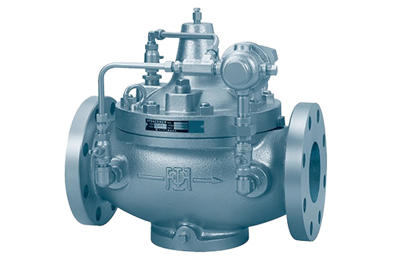
Structure and Dimensions
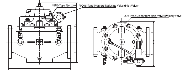
Dimensions and Weight
| Specification | Label | Nominal Diameter | |||||||||
|---|---|---|---|---|---|---|---|---|---|---|---|
| 40 | 50 | 65 | 80 | 100 | 125 | 150 | 200 | 250 | 300 | ||
| Valve Body Cast Iron JIS 10K | L | 220 | 260 | 290 | 330 | 390 | 470 | 530 | 670 | 800 | 900 |
| H₁ | 75 | 90 | 97 | 110 | 125 | 155 | 175 | 220 | 275 | 333 | |
| H₂ | 247 | 268 | 268 | 268 | 268 | 298 | 332 | 424 | 538 | 640 | |
| A | 130 | 142 | 153 | 163 | 193 | 214 | 231 | 270 | 320 | 375 | |
| E | 87 | 93 | 105 | 125 | 147 | 177 | 207 | 265 | 320 | 375 | |
| Weight | 16 | 20 | 32 | 39 | 62 | 94 | 138 | 240 | 420 | 695 | |
| Valve Body Cast Iron JIS 16K | L | 220 | 260 | 290 | 330 | 390 | 470 | 530 | 670 | 800 | 900 |
| Valve Body Cast Bronze JIS 20K | L | 216 | 260 | 286 | 330 | 390 | 480 | 536 | 684 | 816 | 916 |
Disassembly & Maintenance Space Requirements
| Nominal Diameter | 40 | 50 | 65 | 80 | 100 | 125 | 150 | 200 | 250 | 300 |
|---|---|---|---|---|---|---|---|---|---|---|
| Upward Clearance from Pipe Center (mm) | 380 | 390 | 430 | 470 | 480 | 490 | 520 | 650 | 870 | 1040 |
Piping Example
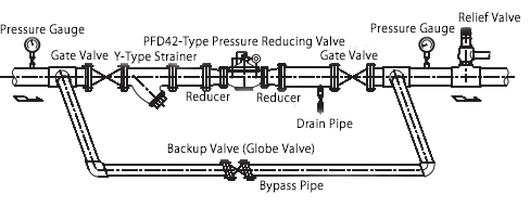
The installation orientation can be either horizontal or vertical piping. However, avoid installing the valve in a water-inverted position or horizontal-facing downward position.
It is recommended to have a straight pipe section of at least:
- 600mm (for nominal diameter 40)
- 900mm (for nominal diameters 50–100)
- 1200mm (for nominal diameters 125, 150)
- 1600mm (for nominal diameters 200, 250)
- 2000mm (for nominal diameter 300)
before and after the pressure-reducing valve for optimal performance
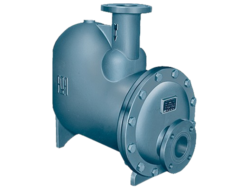
Compound Function Pressure Reducing Valve
It functions as a pressure reducing valve, and when the primary-side pressure drops to a certain level, it opens regardless of the secondary-side pressure to prevent the primary-side pressure from falling below a specified limit.
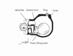
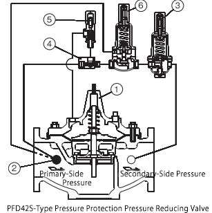
Component Names
| No. | Component Name |
|---|---|
| 1 | OD3-Type Diaphragm Main Valve |
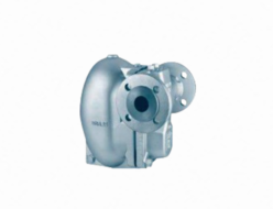
| 2 | FL14-Type Strainer |
| 3 | PPD48-Type Pressure Reducing Valve |
| 4 | NSN3-Type Ejector |
| 5 | QRH5-Type Flow Control Valve |
| 6 | RPD52-2-Type Back Pressure Valve |
Note: The QRH5-Type Flow Control Valve (⑤) is not installed on nominal diameters 100 to 300.