Fushiman Co.
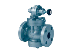
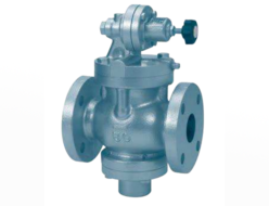
Fushiman PLG61-2 Pressure Reducing Valves
Manufacturer: Fushiman Co.,LTD.
Model: PLG61-2
| Model | Nominal Diameter | Primary Pressure | Secondary Side Setting Range | Maximum Operating Temperature | Body Material | Connection |
|---|---|---|---|---|---|---|
| PLG61-2 | 15〜50 | MAX. 400kPa | 0.5~20kPa | 80℃ | FC,SCPH,SCS | Flange |
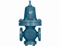
- PMD31L Type Pressure Relief Valve is used for low-pressure applications.
- Since a secondary balance method is used, the secondary side pressure is hardly affected by variations in the primary side pressure. In addition, the balance section uses diaphragms and bellows, so there is no risk of friction or leakage.
- The valve body uses sealing rubber, so the sealing performance when closing is excellent.
- For nominal diameters of 65 and above, please use the PRL Type Pressure Relief Valve.
Specifications and Materials
| Fluid | Pressure kPa | Tempera- ture (°C) | Main Materials | Pipe Connec- tion | |||||
|---|---|---|---|---|---|---|---|---|---|
| Primary Side | Secondary Side Setting Range | Valve Body | Diaphragm Chamber Body | Spring Protection Tube | Valve Seat | Valve Body Diaphragm | |||
| Air and other non-corrosive gases | 2.5 to 400 | 0.5 – 1.4 1.2 – 3.3 3.0 – 8.0 7.0 – 20 | 0 – 80 | Cast Iron | Rolled Steel | Cast Iron | Stainless Steel | Synthetic Rubber | Flange JIS 10K Full Face |
Notes:
- The valve body and box are also available in stainless steel or cast steel.
- ASME Class 150 is available for nominal diameters 20, 25, 40, and 50.
- The body and diaphragm are standard with NBR (nitrile rubber), but FKM (fluoro rubber) and Kalrez® are also available.
- The primary side pressure can be made up to 0.7 MPa (the secondary set range will be 1.4-3.3, 3.0-8.0, and 7.0-18 kPa).
- The connection part is also available in non-rubber and non-copper alloy versions.
Performance
(Reference: 1 kPa = 100 mm of water column)
| Minimum Set Differential Pressure | 2.0kPa |
|---|---|
| Offset (1) | 15% or less of the set pressure (minimum value 0.3kPa) |
| Closing Pressure Rise | 0.4kPa or less (Nominal diameters 15, 20, 25) 1.5kPa or less (Nominal diameters 32, 40, 50) |
| Minimum Adjustable Flow Rate (2) (3) | Nominal diameters 15, 20, 25: 0.5 to 2m³/h (Standard Conditions) Nominal diameters 32, 40, 50: 5 to 10m³/h (Standard Conditions) |
| Valve Seat Leakage | 0.01% or less of rated flow rate |
Notes:
- The pressure conditions may cause an increase of more than 15%.
- The larger the difference between the primary side pressure and the set pressure, the greater it becomes.
- It is independent of the type of gas.
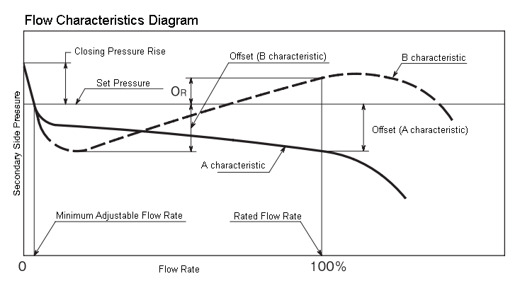
Note:
Generally, it shows the A characteristic, but for nominal diameters 15–25, when the difference between the primary side pressure and the set pressure is large, it shows the B characteristic. In the B characteristic, there may be a case where the O-ring becomes the maximum, in which case the O-ring becomes the offset.
CV Value
| Nominal Diameter | 15 | 20 | 25 | 32 | 40 | 50 |
|---|---|---|---|---|---|---|
| Cv | 1.8 | 2.6 | 3.9 | 6.3 | 8.3 | 13 |
For selected nominal diameters, there are restrictions on the maximum flow rate, in addition to the Cv value. For details, please refer to the section on nominal diameter selection on the following page.
Structure and Dimensions
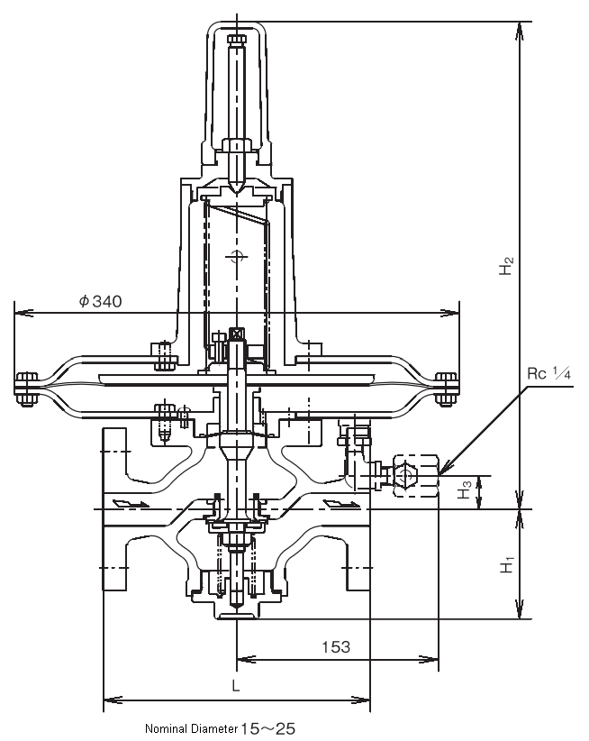
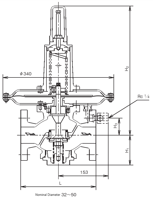
Dimensions and Mass
(mm, kg)
| Nominal Diameter | L | H1 | H2 | H3 | Mass | ||
|---|---|---|---|---|---|---|---|
| Valve Body Cast Iron | Cast Steel & Stainless Steel Cast Steel | Valve Body Cast Iron | Cast Steel & Stainless Steel Cast Steel | ||||
| 15 | 180 | 180 | 81 | 368 | 25 | 18.5 | 20 |
| 20 | 185 | 185 | 81 | 368 | 25 | 18.5 | 20 |
| 25 | 196 | 196 | 84 | 372 | 30 | 20 | 21 |
| 32 | 220 | 230 | 92 | 395 | 53 | 23 | 25 |
| 40 | 220 | 230 | 92 | 395 | 53 | 24 | 25 |
| 50 | 230 | 230 | 92 | 395 | 53 | 25 | 27 |
Note:
In the case of JPI and ASME, the face dimension method differs slightly.
Disassembly and Maintenance Space Required
(mm)
| Nominal Diameter | 15 – 50 |
|---|---|
| From Pipe Center to Above | 600 |
| From Pipe Center to Below | 320 |
Related Products
-
Fushiman P260 Pressure Reducing Valves (Valve Box Stainless Steel Casting: Oil-Prohibited Finish)
-
Fushiman P260 Pressure Reducing Valves – Contained Trap
-
Fushiman A.W. type pressure reducing valve
-
Fushiman SFD42 type back pressure valve (sustain valve) for liquids
-
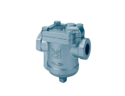
Fushiman B-10C type bucket trap for steam
-
Fushiman J102 type ball joint (for high pressure)
REQUEST QUOTATION

PAYMENT

LINK


