Fushiman Co.
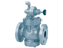
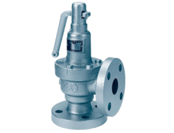
Fushiman PMD31L Pressure Reducing Valves
Manufacturer: Fushiman Co.,LTD.
Model: PMD31L
| Model | Nominal Diameter | Primary Pressure | Secondary Side Setting Range | Maximum Operating Temperature | Body Material | Connection |
|---|---|---|---|---|---|---|
| PMD31L | 15〜150 | MAX. 0.4MPa | 0.01~0.05MPa | 80℃ | FC,SCPH,SCS | Flange |
- It is stable in operation due to the direct-acting pressure regulator.
- It is for low pressure use with the PMD31 type pressure regulator.
- Due to the use of a balanced pressure method, the secondary side pressure is hardly affected by changes in the primary side pressure.
- Because synthetic rubber is used in the body, the stop during valve closure is excellent.
Specifications and Materials
| Fluid | Pressure MPa | Tempera-ture °C | Main Material Parts | Pipe Connec-tion | ||||||
|---|---|---|---|---|---|---|---|---|---|---|
| Primary Side | Secon-dary Side Setting Range | Valve Box | Diaphragm Retainer Liner | Valve Body Diaphragm | Valve Seat | Valve Stem | Spring Protec-tion Tube | |||
| Air and Non-corrosive Gases | 0.02 – 0.4 | 0.01 – 0.05 | 0 – 80 | Cast Iron | Bronze or Stainless Steel | Synthetic Rubber | Bronze or Stainless Steel | Stainless Steel | Cast Iron | Flange JIS10K Flat Seat |
| Cast Steel | ||||||||||
| Stainless Steel Cast Steel | Stainless Steel | Stainless Steel | ||||||||
Remarks:
- ASME Class 150 is also available.
- If the valve box is made of cast steel or stainless steel, the connection part can be manufactured without the use of rubber and with the use of bronze or alloy. Additionally, the specifications and performance of the connection part when rubber is not used will be examined accordingly.
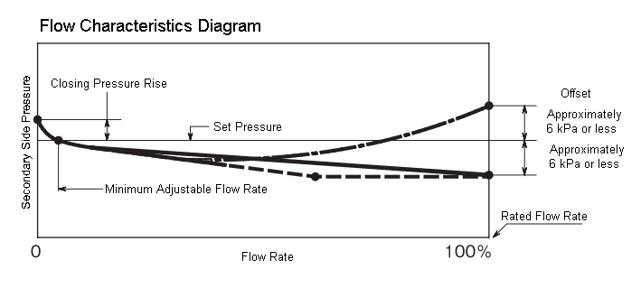
Performance
| Minimum Set Differential Pressure | 0.01 MPa |
|---|---|
| Offset | Approximately 6 kPa or less |
| Closing Pressure Rise | Approximately 3–7 kPa (1) |
| Minimum Adjustable Flow Rate (Air) (2) | Approximately 3–8 m³/h (Standard conditions) (1) |
| Seat Leakage | 0.01% or less of the rated flow rate |
Notes:
- The greater the difference between the primary side pressure and the set pressure, the larger it becomes.
- For gases other than air, divide by √G (where G is the specific gravity of the gas, with air as 1).
CV Value
| Nominal Diameter | 15 | 20 | 25 | 32 | 40 | 50 | 65 | 80 | 100 | 125 | 150 |
|---|---|---|---|---|---|---|---|---|---|---|---|
| Cv | 1.8 | 2.6 | 3.9 | 6.3 | 8.3 | 13 | 21 | 29 | 50 | 76 | 109 |
Structure and Dimensions
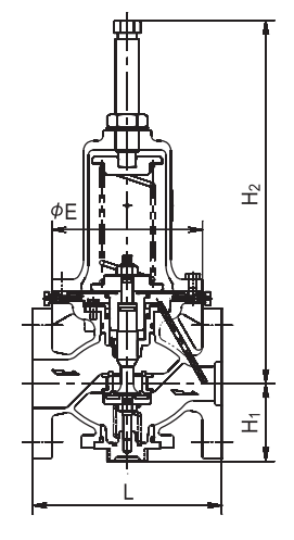
Dimensions and Mass
(mm, kg)
| Nominal Diameter | Valve Body: Cast Iron | Valve Body: Cast Steel or Stainless Steel Cast Steel | ||||||||
|---|---|---|---|---|---|---|---|---|---|---|
| L | H1 | H2 | E | Mass | L | H1 | H2 | E | Mass | |
| 15 | 196 | 70 | 364 | 155 | 12 | 206 | 70 | 364 | 155 | 16 |
| 20-25 | 200 | 70 | 364 | 155 | 13 | 210 | 70 | 364 | 155 | 17 |
| 32 | 175 | 70 | 364 | 155 | 14 | 220 | 70 | 364 | 155 | 18 |
| 40 | 190 | 80 | 374 | 155 | 16 | 220 | 80 | 374 | 155 | 21 |
| 50 | 195 | 80 | 374 | 155 | 17 | 225 | 80 | 374 | 155 | 22 |
| 65 | 230 | 110 | 488 | 210 | 34 | 280 | 109 | 488 | 210 | 38 |
| 80 | 250 | 110 | 488 | 210 | 35 | 280 | 109 | 488 | 210 | 39 |
| 100 | 290 | 127 | 537 | 250 | 58 | 330 | 121 | 542 | 250 | 65 |
| 125 | 365 | 174 | 690 | 320 | 98 | 380 | 174 | 690 | 320 | 114 |
| 150 | 415 | 207 | 902 | 380 | 150 | 470 | 207 | 902 | 380 | 162 |
Disassembly and Maintenance Space Required
| Nominal Diameter | 15-32 | 40-50 | 65-80 | 100 | 125 | 150 |
|---|---|---|---|---|---|---|
| Above Pipe Center | 520 | 530 | 650 | 720 | 1010 | 1330 |
| Below Pipe Center | 190 | 200 | 340 | 400 | 450 | 550 |
Related Products

REQUEST QUOTATION

PAYMENT

LINK


