Fushiman Co.
Fushiman PMD31P/LP And PLG61-2P Hybrid Pressure Reducing Valves

Manufacturer: Fushiman Co.,LTD.
Model: PMD31P/LP And PLG61-2P
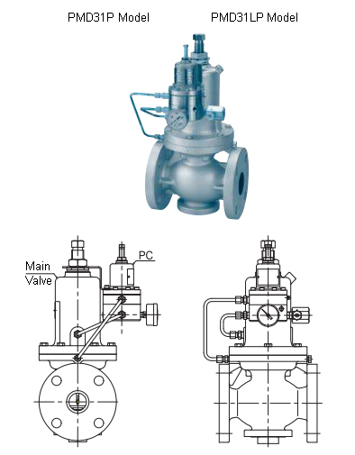
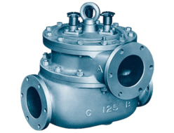
PMD31P Type Pressure Reducing Valve for Gas
| Model | Nominal Diameter | Primary Pressure | Secondary Pressure Range | Max Operating Temperature | Main Body Material | Connection |
|---|---|---|---|---|---|---|
| PMD31P | 15~100 | MAX. 1.0MPa | 0.035~0.7MPa | 80℃ | FC | Flange |
PMD31LP Type Pressure Reducing Valve for Gas
| Model | Nominal Diameter | Primary Pressure | Secondary Pressure Range | Max Operating Temperature | Main Body Material | Connection |
|---|---|---|---|---|---|---|
| PMD31LP | 15~100 | MAX. 0.4MPa | 0.01~0.05MPa | 80℃ | FC | Flange |
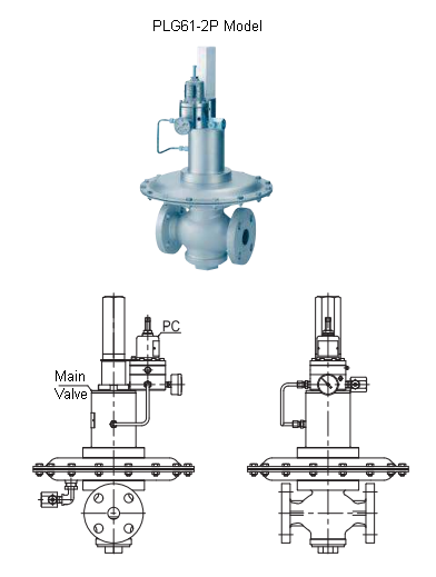
PLG61-2P Type Pressure Reducing Valve for Gas
| Model | Nominal Diameter | Primary Pressure | Secondary Pressure Range | Max Operating Temperature | Main Body Material | Connection |
|---|---|---|---|---|---|---|
| PLG61-2P | 15~50 | MAX. 400kPa | 0.5~20kPa | 80℃ | FC | Flange |
PMD31P Type Pressure Reducing Valve for Liquid Use
| Model | Nominal Diameter | Primary Pressure | Secondary Pressure Range | Max Operating Temperature | Main Body Material | Connection |
|---|---|---|---|---|---|---|
| PMD31P | 15〜100 | MAX. 1.0MPa | 0.035~0.7MPa | 80℃ | FC | Flange |
New Product
- Maintains the characteristics of a self-operated pressure reducing valve that responds sensitively and accurately to load fluctuations while achieving an offset comparable to other valves.
- Compared to conventional models, it offers an increase in nominal flow rate (Cv value) (our company’s product). However, considering pipeline flow velocity, the Cv value remains the same as conventional products with the same nominal diameter.
- Can be installed on existing valves, allowing for easy performance improvement.
- Useful when replacing self-operated valves in large-scale systems while maintaining adjustment accuracy.
- Can also be used for applications such as back pressure and steam control in vacuum and low-pressure pressure reducing valves.
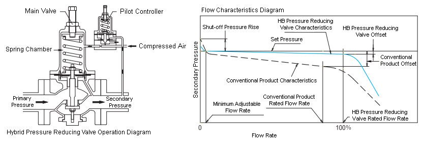
The hybrid pressure reducing valve achieves control precision comparable to other valves by simply adding an innovative pilot controller to a conventional self-operated pressure reducing valve.
In conventional self-operated pressure reducing valves, achieving both minimal offset and high adjustment accuracy can be challenging. Additionally, when pressure reduction through self-operated control becomes complex, or when simplified installation with highly precise pressure reduction is desired, the hybrid pressure reducing valve is the optimal solution.
1. Type of Equipment
1.1 Hybrid Pressure Reducing Valve
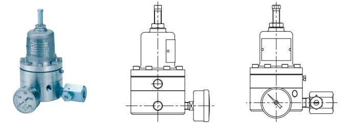
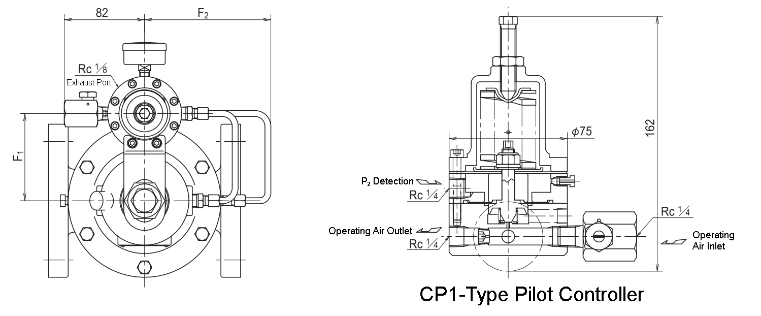
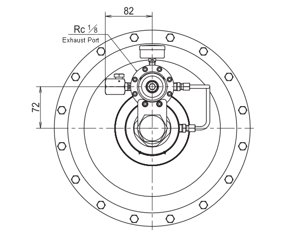
1.2 CP1 Model Pilot Controller (PC)
2. Operation Explanation
The Hybrid (HB) Pressure Reducing Valve consists of two components: the main valve, which controls pressure, and the pilot controller (PC), which adjusts the control fluid based on changes in secondary pressure. The pilot controller is supplied with a control fluid such as compressed air, and its output is connected to the main valve’s diaphragm chamber.
The main valve automatically adjusts its opening according to the secondary pressure, similar to a conventional pressure reducing valve. However, the opening fluctuates in response to pressure changes (smaller when fully open, larger when slightly open), which causes an offset.
The pilot controller operates by opening to release the control fluid externally when the secondary pressure is high and closing to send the control fluid to the main valve when the secondary pressure is low. Since the main valve and the pilot controller operate almost simultaneously, the secondary pressure remains stable even when load fluctuations occur.
3. Specifications and Materials
| Hybrid Pressure Reducing Valve Model | PMD31P | PMD31LP | PLG61-2P | |
|---|---|---|---|---|
| Main Valve Section | Model | PMD31 | PMD31L | PLG61-2P |
| Fluid | Gas • Liquid | Gas | Gas | |
| Nominal Diameter | 15–100 | 15–100 | 15–50 | |
| Primary Pressure | 0.055–1.0 MPa | 0.02–0.4 MPa | 2.5–400 kPa | |
| Set Pressure Range | 15–80A: 0.035–0.3, 0.2–0.7 MPa 100A: 0.035–0.3, 0.2–0.55 MPa | 10–50 kPa | 0.5–1.4, 1.2–3.3, 3.0–8.0, 7.0–20 kPa | |
| Temperature | 0–80°C | |||
| Major Materials | Please refer to each main valve catalog. | |||
| PC Section | Operating Fluid | Air | ||
| Operating Pressure | 140–250 kPa (1) | 100 kPa | 20–40 kPa (1) | |
| Air Consumption | Approximately 2002 L/h (Standard Condition) | Approximately 402 L/h (Standard Condition) | ||
| Connection Port | JIS Rc1/4 (Threaded) | |||
| Major Materials | Body & Valve: Stainless Steel, Spring Protection Tube: Aluminum Alloy, Diaphragm: Synthetic Rubber, Throttle Valve & Piping: Copper Alloy | |||
Note (1): The operating pressure varies depending on the set pressure.
4. Performance and Cv Value
| Hybrid Pressure Reducing Valve Model | PMD31P (PMD31LP) | PLG61-2P | ||||||||||||||
|---|---|---|---|---|---|---|---|---|---|---|---|---|---|---|---|---|
| Nominal Diameter | 15 | 20 | 25 | 32 | 40 | 50 | 65 | 80 | 100 | 15 | 20 | 25 | 32 | 40 | 50 | |
| Cv Value | 1.8 | 2.6 | 4.5 | 7.0 | 10.1 | 18 | 28.1 | 35 | 55 | 1.8 | 2.6 | 3.9 | 6.3 | 8.3 | 13 | |
| Performance | Minimum Set Differential Pressure | 10 kPa (5 kPa) | 2 kPa | |||||||||||||
| Offset | Below 5 kPa (Below 1 kPa) | Below 10 kPa (Below 2 kPa) | Below 0.1 kPa | |||||||||||||
| Shutoff Pressure Increase | Below 5 kPa (Below 2 kPa) | Below 5 kPa (Below 2 kPa) | Below 0.2 kPa (3) | |||||||||||||
| Minimum Adjustable Flow Rate | Please refer to each main valve catalog. | |||||||||||||||
| Seat Leakage | Below 0.01% of the rated valve flow rate | |||||||||||||||
Note (2): The values vary depending on the set pressure and the piping conditions before and after the valve.
Note (3): The values may increase depending on the main valve settings.
5. Structure, Dimensions, and Mass
5.1 Structure, Dimensions, and Mass of PMD31P and PMD31LP Models
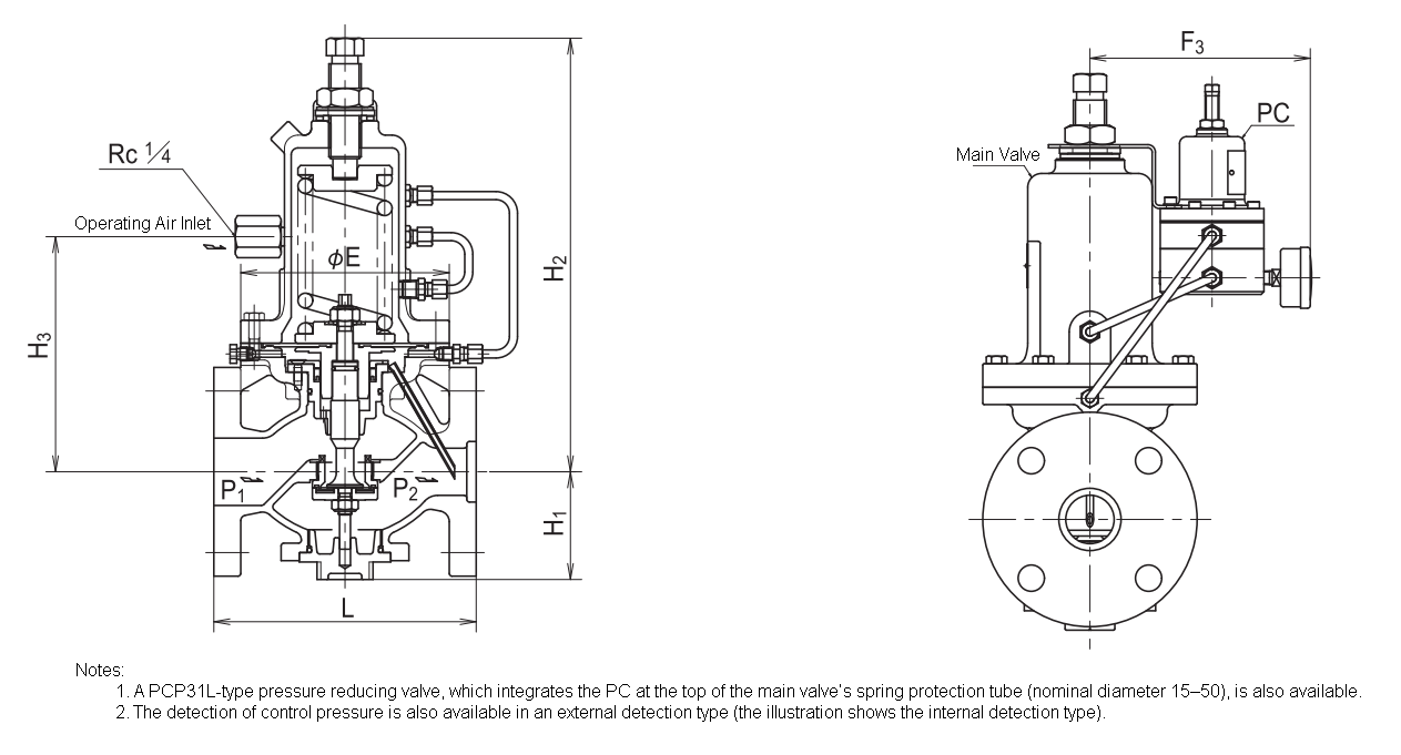
Dimensions and Mass (mm, kg)
| Nominal Diameter | L | Hi | h2 | h3 | E | Fi | F2 | f3 | Mass | Main Valve: Pipe Connection, Valve Box Material: Cast Iron | |
|---|---|---|---|---|---|---|---|---|---|---|---|
| PMD31P | PMD31LP | ||||||||||
| 15 | 196 | 70 | 314 | 358 | 165 | 155 | 88 | 128 | 159 | 15 | Flange Type JIS10K Full Face |
| 20 | 200 | 70 | 314 | 358 | 165 | 155 | 88 | 128 | 159 | 16 | |
| 25 | 200 | 70 | 314 | 358 | 165 | 155 | 88 | 128 | 159 | 16 | |
| 32 | 175 | 70 | 314 | 358 | 165 | 155 | 88 | 128 | 159 | 17 | |
| 40 | 190 | 80 | 322 | 368 | 175 | 155 | 88 | 128 | 159 | 19 | |
| 50 | 195 | 80 | 322 | 368 | 175 | 155 | 88 | 128 | 159 | 20 | |
| 65 | 230 | 104 | 422 | 481 | 254 | 210 | 109 | 156 | 180 | 37 | |
| 80 | 250 | 104 | 422 | 481 | 254 | 210 | 109 | 156 | 180 | 38 | |
| 100 | 290 | 127 | 456 | 529 | 289 | 250 | 126 | 176 | 197 | 61 | |
Note: Valve box materials made of bronze or cast stainless steel are also available.
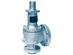
5.2 Structure, Dimensions, and Mass of PLG61-2P Pressure Reducing Valve
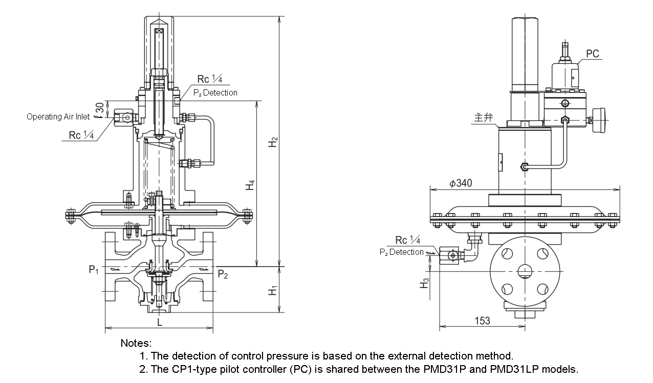
Dimensions and Mass (mm, kg)
| Nominal Diameter | L | Hi | h2 | h3 | h4 | Mass | Main Valve: Pipe Connection, Valve Box Material: Cast Iron |
|---|---|---|---|---|---|---|---|
| 15 | 180 | 81 | 451 | 25 | 298 | 23.5 | Flange Type JIS10K Full Face |
| 20 | 185 | 81 | 451 | 25 | 298 | 23.5 | |
| 25 | 196 | 84 | 455 | 30 | 302 | 25 | |
| 32 | 220 | 92 | 478 | 53 | 325 | 28 | |
| 40 | 220 | 92 | 478 | 53 | 325 | 29 | |
| 50 | 230 | 92 | 478 | 53 | 325 | 30 |
6. Piping Example
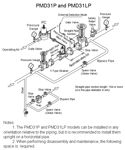
(mm)
| Nominal Diameter | 15–32 | 40 • 50 | 65–80 | 100 |
|---|---|---|---|---|
| Above Piping Center | 520 | 530 | 650 | 720 |
| Below Piping Center | 190 | 200 | 340 | 400 |

(mm)
| Nominal Diameter | 15〜50 |
|---|---|
| Above Piping Center | 520 |
| Below Piping Center | 190 |
7. Precautions for Use
- Before use, please read the “Instruction Manual” carefully.
- When piping for operating air, always perform a blow operation before connection to completely remove scale and debris.
- Supply constant pressure operating air to the pilot controller (PC) using a pressure reducing valve with a filter.
- Ensure that the exhaust port of the pilot controller is not blocked.
- When using the PMD31P model with liquid, be sure to completely remove any trapped air inside at the start of water flow.
Related Products

REQUEST QUOTATION

PAYMENT

LINK


