Fushiman Co.
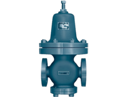
Fushiman PRL Pressure Reducing Valves
Manufacturer: Fushiman Co.,LTD.
Model: PRL
| Model | Nominal Diameter | Primary Pressure | Secondary Side Setting Range | Maximum Operating Temperature | Body Material | Connection |
|---|---|---|---|---|---|---|
| PRL | 65〜150 | MAX. 500kPa | 1~50kPa | 80℃ | FC,SCPH,SCS | Flange |
- Low-pressure, automatic diaphragm-type pressure relief valve for air.
- For large flow (Nominal diameter 65–150).
- For small flow (Nominal diameter 15–50), please use PLG61-2 type pressure relief valve or PMD31L type pressure relief valve.
Specifications and Materials
| Fluid | Nominal Diameter | Pressure kPa | Tempera- ture (°C) | Main Material | Pipe Connec- tion | |||
|---|---|---|---|---|---|---|---|---|
| Primary Side | Secondary Set Range | Valve Body | Valve Body & Valve Seat | Diaphragm | ||||
| Air and other non-corrosive gases | 65–150 | 500 or less | 1.0–50 (2) | 0–80 | Cast Iron | Stainless Steel | Synthetic Rubber | Flange JIS 10K Full Face |
Note:
- The size of the top work (adjustment part) may vary. Please refer to the “Secondary Set Pressure Range (Spring section)” and the “Maximum Differential Pressure by Top Work Type” below.
- This entire range cannot be covered by one screw. Please refer to the “Secondary Set Pressure Range (Spring section)” and “Top Work Type Maximum Differential Pressure” below.
Additional Information:
The valve body can be made of either cast steel or stainless steel. In this case, ASME Class 150 is also available.
Secondary Set Pressure Range (Spring section) and Maximum Differential Pressure by Top Work Type Table
| Nominal Diameter | Top Work Type and ΔP MAX (kPa) | Set Pressure Range (kPa) | 1.0 or more – 1.5 or less | More than 1.5 – 2.0 or less | More than 2.0 – 3.0 or less | More than 3.0 – 5.0 or less | More than 5.0 – 7.0 or less | More than 7.0 – 10.0 or less | More than 10 – 15 or less | More than 15 or less | More than 15 or less | More than 15 or less |
|---|---|---|---|---|---|---|---|---|---|---|---|---|
| 65 | Top Work Type | A | B | B | B | C | C | D | D | E | E | |
| ΔP MAX. | 150 | 130 | 200 | 340 | 300 | 430 | 420 | 500 | 500 | 500 | ||
| 80 | Top Work Type | A | A | B | B | B | C | D | D | D | E | |
| ΔP MAX. | 140 | 180 | 180 | 290 | 410 | 380 | 370 | 490 | 500 | 500 | ||
| 100 | Top Work Type | A | A | A | B | B | C | C | C | D | D | |
| ΔP MAX. | 110 | 140 | 220 | 240 | 330 | 300 | 460 | 500 | 500 | 500 | ||
| 125 | Top Work Type | A | A | A | A | A | B | C | C | D | D | |
| ΔP MAX. | 84 | 110 | 170 | 280 | 390 | 360 | 350 | 470 | 460 | 480 | ||
| 150 | Top Work Type | A | A | A | A | A | B | C | C | D | D | |
| ΔP MAX. | 68 | 90 | 140 | 230 | 310 | 290 | 280 | 380 | 370 | 390 | ||
Note:
By adding the maximum differential pressure (ΔP MAX) to the set pressure, the allowable maximum primary side pressure is obtained. However, the maximum allowable pressure for the secondary side is 500 kPa.
Example 1: If the nominal diameter is 100 and the set pressure is 10 kPa, adding the ΔP MAX from Top Work C results in a primary side pressure of 10 + 300 = 310 kPa.
Example 2: If the nominal diameter is 80 and the set pressure is 20 kPa, adding the ΔP MAX from Top Work D results in a primary side pressure of 20 + 490 = 510 kPa, which exceeds 500 kPa, so it becomes limited to 500 kPa.
Performance
| Pressure Ratio | Varies depending on set pressure and top work type. (Refer to the “Secondary Set Pressure Range (Spring section) and Maximum Differential Pressure by Top Work Type” table above) |
|---|---|
| Offset | Less than 12% of the maximum set pressure |
| Closing Pressure Rise | Less than 20% of the maximum set pressure |
| Minimum Adjustable Flow Rate | Less than 5% of the rated flow rate |
| Valve Seat Leakage | Less than 0.5% of the rated flow rate |
CV Value
| Nominal Diameter | 65 | 80 | 100 | 125 | 150 |
|---|---|---|---|---|---|
| CV | 35 | 46 | 72 | 123 | 178 |
Structure and Dimensions
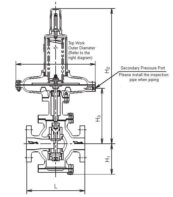
Structure and Dimensions
(mm, kg)
| Nominal Diameter | 65 | 80 | 100 | 125 | 150 | |
|---|---|---|---|---|---|---|
| L | 240 | 270 | 310 | 360 | 380 | |
| H1 | 141 | 146 | 173 | 203 | 222 | |
| H2 | 590 | 602 | 630 | 675 | 694 | |
| h3 | 248 | 260 | 288 | 333 | 352 | |
| Weight (kg) | Cast Iron | 57 | 65 | 81 | 104 | 122 |
| Cast Steel | 66 | 75 | 93 | 120 | 140 | |
Note
(4) This shows the case for Top Work Type C.
Top Work Outer Diameter
(mm, kg)
| Type | A | B | C | D | E | |
|---|---|---|---|---|---|---|
| Outer Diameter | 610 | 500 | 410 | 340 | 290 | |
| Weight Increase/Decrease (5) | Cast Iron | +27 | +12 | 0 | -7 | -10 |
| Cast Steel | +31 | +14 | 0 | -8 | -12 | |
Note
(5) When the top work is other than type C, the values from the table above may be added or subtracted.
Related Products
-

Fushiman NFD1 type ejector
-
Fushiman PPD41B/PPD41B-3 Pressure Reducing Valves (High-Pressure Gas Equipment Certified Product)
-
Fushiman RPF13 type lift type safety relief valve
-
Fushiman PPD48 Type Pressure Reducing Valve
-
Fushiman BFF27 type large volume steam trap
-
Fushiman All fluids AWR type back pressure valve
REQUEST QUOTATION

PAYMENT

LINK


