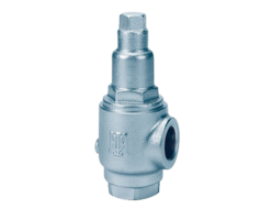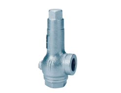
The diaphragm-sealed disc design makes it less prone to malfunctions caused by disc (valve body) sticking.
The disc uses synthetic rubber, ensuring a good seal when the valve is closed.
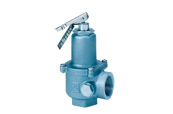
The set pressure can be easily adjusted without removing the lever.
Structurally and materially, there is no risk of cracks due to low-temperature embrittlement.
Specifications and Materials
| Shape | Diaphragm Seal Type | |
| Fluid | Water, Hot Water | |
| Pressure | Set Pressure: 0.05–1.6 MPa (Back Pressure: Atmospheric Pressure) | |
| Operating Temperature | 0–100°C | |
| Material | Lever | Malleable Iron |
| Adjustment Screw | Brass | |
| Spring Seat | Malleable Iron | |
| Lift Rod | Stainless Steel | |
| Adjustment Spring | Spring Steel, Piano Wire | |
| Spring Protection Tube | Cast Bronze | |
| Diaphragm Holder | Stainless Steel | |
| Diaphragm Valve Body | Synthetic Rubber | |
| Valve Box | Blue Silk | |
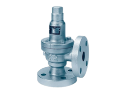
| Pipe Flange | Cast Bronze | |
| Application | Pressure Vessels, Secondary Side of Pressure Reducing Valves, Other Piping Protection | |
- The outlet-side pressure (back pressure) is atmospheric pressure. Avoid installing outlet-side pipes (drain pipes) that rise vertically or exceed 4.5 meters in length.
- The end of the drain pipe should be positioned at least 15 cm above the surface of the drainage channel. If it is necessary to discharge blow-off water or other liquids, install a separate discharge pipe and leave at least 15 cm of space at the drain pipe’s end.
- Occasionally (about once per day), move the lever to check if discharge occurs. If the outlet-side pipe is 15 cm or longer, slightly lift the lever handle at an angle to allow liquid to discharge. (If lifted straight up to 90°, the valve may not operate properly due to back pressure effects.) If this happens, fully close the valve once, then reset its operation.
- If there is a risk of freezing, take adequate insulation measures.
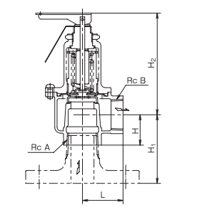
Dimensions and Mass
| Nominal Diameter | Face-to-Face Dimensions | Height (H₂) | Pipe Connection | Weight (kg) | ||||||
| (Inlet × Outlet) | L | H (Screw Type) | H₁ (Flange Type) | A | Inlet | B | Outlet | Screw Type | Flange (Inlet Type) | |
| 15 × 20 | 44 | 33 | 64 | 111 | ½ | JIS Rc Screw Type JIS 16K Full-Faced | ¾ | JIS Rc Screw Type | 1.2 | 2 |
| 20 × 25 | 44 | 33 | 67 | 111 | ¾ | 1 | 1.2 | 2.1 | ||
| 25 × 25 | 44 | 33 | 72 | 111 | 1 | 1.2 | 2.7 | |||
| 32 × 32 | 62 | 43 | 82 | 140 | 1¼ | 1½ | 3 | 5.1 | ||
| 40 × 40 | 62 | 43 | 83 | 140 | 1½ | 3 | 5.4 | |||