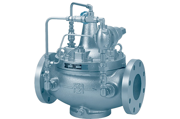
Notes:
- The valve box can also be made of stainless steel cast steel.
- ASME Class 150 and 300 can also be manufactured.
- Valve boxes with a nylon coating (for temperatures of 60°C or lower) can also be manufactured.
- For water hammer prevention, please use the SFD42 type (refer to page 110).
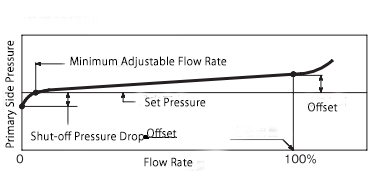
Performance
| Maximum Differential Pressure Setting | 1.5 MPa |
|---|---|
| Minimum Differential Pressure Setting | 0.04 MPa |
| Offset | Approximately 10% or less of the set pressure (minimum value: ~0.04 MPa) |
| Shutoff Pressure Drop (¹) | 0.01–0.03 MPa (for pressure setting range 0.05–0.25 MPa) |
| 0.02–0.05 MPa (for pressure setting range 0.2–0.65 MPa) | |
| 0.06–0.09 MPa (for pressure setting range 0.6–1.2 MPa) | |
| 0.08–0.12 MPa (for pressure setting range 1.0–2.0 MPa) | |
| Maximum Usable Viscosity Fluid | Light oil 20 mm²/s or lower |
| Minimum Adjustable Flow Rate (Water) (¹) | 5–15 L/min |
| Valve Seat Leakage | 0.01% or less of the rated flow rate |
Note (¹): Applicable under specific operating conditions.
Cv Value
| Nominal Diameter | 40 | 50 | 65 | 80 | 100 | 125 | 150 | 200 | 250 | 300 |
|---|---|---|---|---|---|---|---|---|---|---|
| Cv | 22.5 | 40 | 62.5 | 90 | 160 | 250 | 360 | 640 | 1000 | 1440 |
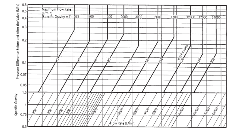
| Maximum Flow Rate (Water) (L/min) (²) | 533 | 800 | 1300 | 2000 | 3000 | 5000 | 7700 | 12000 | 17000 | 24000 |
Note (²): For liquids other than water, divide by √γ (γ = specific gravity of the liquid, assuming water at 4°C as 1).
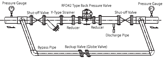
Piping Example
Space Required for Disassembly and Maintenance
| Nominal Diameter | 40 | 50 | 65 | 80 | 100 | 125 | 150 | 200 | 250 | 300 |
|---|---|---|---|---|---|---|---|---|---|---|
| Upward Space from Pipe Center (mm) | 450 | 460 | 470 | 480 | 500 | 530 | 570 | 670 | 870 | 1040 |
The installation orientation can be either horizontal or vertical piping. However, avoid installing it upside down or horizontally on its side.
It is recommended to install a straight pipe section of at least:
- 600 mm (for nominal diameter 40)
- 900 mm (for nominal diameters 50–100)
- 1200 mm (for nominal diameters 125–150)
- 1600 mm (for nominal diameters 200–250)
- 2000 mm (for nominal diameter 300)
before and after the back pressure valve to ensure stable operation.
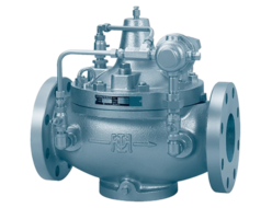
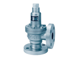
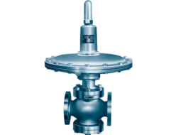
Structure and Dimensions
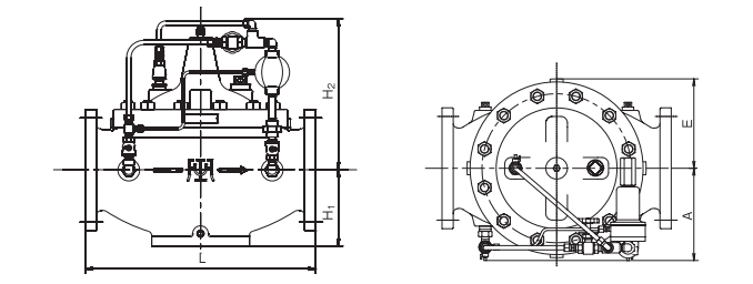
Dimensions and Weight
| Specification/Nominal Diameter | Label | 40 | 50 | 65 | 80 | 100 | 125 | 150 | 200 | 250 | 300 |
| Valve Box Cast Iron (JIS 10K) | L | 220 | 260 | 290 | 330 | 390 | 470 | 530 | 670 | 800 | 900 |
| H1 | 75 | 90 | 97 | 110 | 125 | 155 | 175 | 220 | 275 | 333 | |
| H2 | 260 | 280 | 300 | 300 | 320 | 320 | 345 | 424 | 538 | 640 | |
| A | 110 | 120 | 135 | 145 | 180 | 200 | 220 | 270 | 320 | 375 | |
| E | 125 | 113 | 105 | 125 | 147 | 177 | 207 | 258 | 310 | 370 | |
| Weight | 16 | 20 | 32 | 39 | 62 | 94 | 138 | 240 | 420 | 695 | |
| Valve Box Cast Iron (JIS 16K) | L | 220 | 260 | 290 | 334 | 394 | 474 | 534 | 678 | 808 | 908 |
| Valve Box Cast Steel / Stainless Steel Cast Steel (JIS 20K) | L | 216 | 260 | 286 | 330 | 390 | 480 | 536 | 684 | 816 | 916 |
Nominal Diameter Selection
Please select the appropriate nominal diameter using the nominal diameter selection chart.