Since the outlet pressure balance method is adopted, the primary side pressure is hardly affected by fluctuations in the outlet side pressure.
Since synthetic rubber is used for the valve body, the sealing performance when the valve is closed is excellent.
Specifications and Materials
| Fluid | Nominal Diameter | Primary Side Pressure Range (MPa) | Temperature (℃) | Main Component Materials | Pipe Connection | |||
| Valve Body Spring Cover | Valve Element Diaphragm | Valve Seat Liner | Valve Stem | |||||
| Air and other non-corrosive gases | 15–80 | 0.035–0.3 0.2–0.7 | 0–80 | Cast Iron | Synthetic Rubber | Bronze | Stainless Steel | Flange JIS 10K Full-Face |
| 100 | 0.035–0.3 0.2–0.55 | |||||||
| 125・150 | 0.035–0.4 | |||||||
- Valve housing can also be made of cast bronze or stainless steel casting. In this case, ASME Class 150 can also be manufactured.
- Valve seat can be made without rubber or from bronze as well.
- Products exceeding the specified pressure range can also be manufactured.
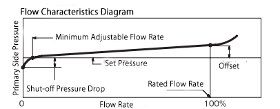
Performance
| Parameter | Value / Description |
|---|---|
| Minimum Set Differential Pressure | 0.02 MPa |
| Offset | 15% or less of the maximum set pressure |
| Shut-off Pressure Drop | 0.01–0.02 MPa |
| Minimum Adjustable Flow Rate | 5–10 m³/h (Standard Condition) |
| Valve Seat Leakage | 0.01% or less of the rated flow rate |
Cv Value
| Nominal Diameter (mm) | 15・20・25 | 32 | 40 | 50 | 65 | 80 | 100 | 125 | 150 |
|---|---|---|---|---|---|---|---|---|---|
| Cv (Flow Coefficient) | 3.9 | 6.3 | 8.3 | 13 | 21 | 29 | 50 | 76 | 109 |
Structure and Dimensions
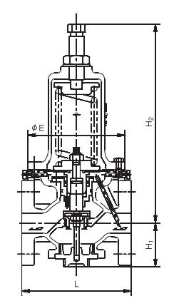
Dimensions and Weight
| Nominal Diameter (mm) | Valve Body: Cast Iron | Valve Body: Cast Bronze or Stainless Steel Casting | ||||||||
|---|---|---|---|---|---|---|---|---|---|---|
| L | H₁ | H₂ | E | Weight (kg) | L | H₁ | H₂ | E | Weight (kg) | |
| 15 | 196 | 70 | 317 | 155 | 12 | 206 | 70 | 317 | 155 | 16 |
| 20 | 200 | 70 | 317 | 155 | 13 | 210 | 70 | 317 | 155 | 17 |
| 25 | 200 | 70 | 317 | 155 | 13 | 210 | 70 | 317 | 155 | 17 |
| 32 | 175 | 80 | 317 | 155 | 14 | 220 | 70 | 317 | 155 | 18 |
| 40 | 190 | 80 | 317 | 155 | 16 | 220 | 80 | 325 | 155 | 21 |
| 50 | 195 | 80 | 325 | 155 | 17 | 225 | 80 | 325 | 155 | 22 |
| 65 | 230 | 104 | 425 | 210 | 34 | 280 | 104 | 425 | 210 | 38 |
| 80 | 250 | 127 | 460 | 250 | 45 | 300 | 127 | 460 | 250 | 50 |
| 100 | 290 | 127 | 460 | 250 | 58 | 330 | 127 | 460 | 250 | 65 |
| 125 | 365 | 174 | 607 | 320 | 98 | 380 | 174 | 607 | 320 | 114 |
| 150 | 415 | 207 | 787 | 380 | 159 | 470 | 209 | 810 | 380 | 170 |
Nominal Diameter Selection
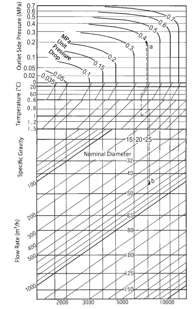
Please select the appropriate nominal diameter using the nominal diameter selection chart.
If the set pressure and outlet pressure fluctuate within a certain range, use the smallest pressure difference for selection.
Example of Use
- Set Pressure: 0.4 MPa
- Outlet Pressure: 0.2 MPa
- Temperature: 60°C
- Gas Mixture (Specific Gravity): 0.8
- Flow Rate: 600 m³/h (Standard Condition)
Selection Process:
- Find the intersection of 0.4 MPa (set pressure) and 0.2 MPa (outlet pressure) on the chart.
- From this point, move downward to the temperature compensation line at 20°C, then adjust it to 60°C.
- Next, move downward from the specific gravity 1.0 line to the specific gravity 0.8 compensation line.
- From here, move downward to find the intersection with 600 m³/h flow rate.
- The intersection falls between nominal diameters 40 and 50, but choosing the larger size is recommended.
- Therefore, nominal diameter 50 is the most suitable selection.
Disassembly and Maintenance Space Requirements
| Nominal Diameter (mm) | 15–32 | 40・50 | 65・80 | 100 | 125 | 150 |
|---|---|---|---|---|---|---|
| Upward Space from Pipe Center (mm) | 470 | 480 | 640 | 730 | 930 | 1220 |
Piping Example
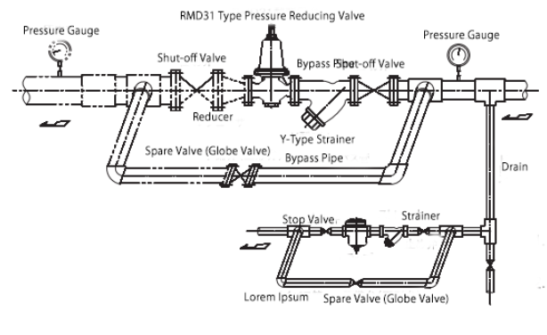
- The installation orientation on the piping is optional. It can be installed on both horizontal and vertical pipes.
- If the fluid is air or similar and the outlet side is open to the atmosphere, the double-dashed line section is not necessary