The system adopts the outlet pressure balance method, so fluctuations in the outlet side pressure hardly affect the primary side pressure.
The valve body uses synthetic rubber, ensuring excellent sealing performance when the valve is closed.
Specifications and Materials
| Fluid | Nominal Diameter | Primary Side Pressure Range (MPa) | Temperature (℃) | Main Component Materials | Pipe Connection | |||
| Valve Body Spring Cover | Valve Element Diaphragm | Valve Seat Liner | Valve Stem | |||||
| Air and other non-corrosive gases | 15–80 | 0.035–0.3 0.2–0.7 | 0–80 | Cast Iron | Synthetic Rubber | Bronze | Stainless Steel | Flange JIS 10K Full-Face |
| 100 | 0.035–0.3 0.2–0.55 | |||||||
| 125・150 | 0.035–0.4 | |||||||
Notes:
Manufacturers can produce valve boxes from cast iron or stainless steel, and in this case, they can also manufacture ASME Class 150.
They can also manufacture valve boxes with a nylon coating for temperatures of 60°C or lower.
They can produce products for applications where rubber cannot be used in the fluid and brass is not allowed.
They can also manufacture products that exceed the specified pressure range.
Performance
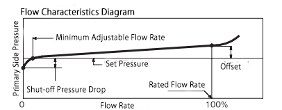
| Minimum Differential Pressure Setting | 0.02 MPa |
|---|---|
| Offset | 0.06 MPa (For nominal diameters 15–40, 65, 125, 150) 0.08 MPa (For nominal diameters 50, 80, 100) |
| Shutoff Pressure Drop | 0.01–0.02 MPa |
| Minimum Adjustable Flow Rate (Water) (¹) | 3–5 L/min |
| Valve Leakage | 0.01% or less of the rated flow rate |
| Maximum Usable Viscosity | 400 mm²/s (under operating temperature conditions) |
Note (¹): For liquids other than water, divide by √γ (γ = specific gravity of the liquid, assuming water at 4°C as 1).
Cv Value
| Nominal Diameter | 15–25 | 32 | 40 | 50 | 65 | 80 | 100 | 125 | 150 |
|---|---|---|---|---|---|---|---|---|---|
| Cv | 3.9 | 6.3 | 8.3 | 13 | 21 | 29 | 50 | 76 | 109 |
| Maximum Flow Rate (Water) (L/min) (²) | 90 | 150 | 204 | 330 | 543 | 767 | 1323 | 2016 | 2892 |
Note (²): For liquids other than water, divide by √γ (γ = specific gravity of the liquid, assuming water at 4°C as 1).
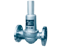
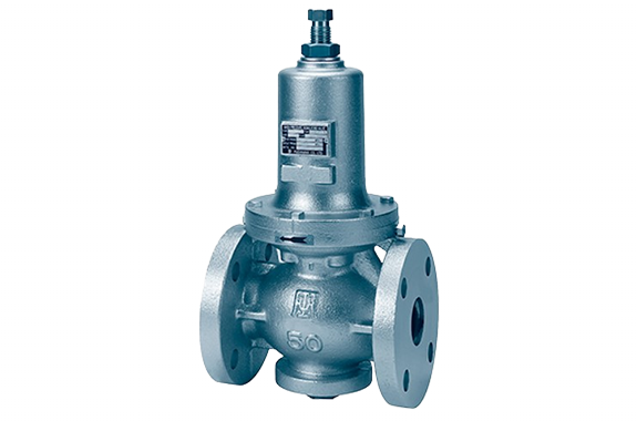
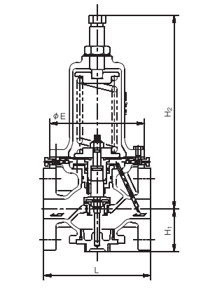
Structure and Dimensions
Dimensions and Weight
| Nominal Diameter | Cast Iron Valve Box | Cast Steel or Stainless Steel Valve Box | ||||||||
|---|---|---|---|---|---|---|---|---|---|---|
| L | H₁ | H₂ | E | Weight | L | H₁ | H₂ | E | Weight | |
| 15 | 196 | 70 | 317 | 155 | 12 | 206 | 70 | 317 | 155 | 16 |
| 20 | 200 | 70 | 317 | 155 | 13 | 210 | 70 | 317 | 155 | 17 |
| 25 | 200 | 70 | 317 | 155 | 13 | 210 | 70 | 317 | 155 | 17 |
| 32 | 175 | 70 | 317 | 155 | 14 | 220 | 70 | 317 | 155 | 18 |
| 40 | 190 | 80 | 325 | 155 | 16 | 230 | 80 | 325 | 155 | 20 |
| 50 | 195 | 80 | 325 | 155 | 17 | 225 | 80 | 325 | 155 | 22 |
| 65 | 230 | 104 | 425 | 210 | 34 | 280 | 104 | 425 | 210 | 38 |
| 80 | 250 | 127 | 460 | 250 | 45 | 290 | 127 | 460 | 250 | 50 |
| 100 | 290 | 127 | 460 | 250 | 58 | 330 | 127 | 460 | 250 | 65 |
| 125 | 365 | 174 | 607 | 320 | 98 | 380 | 174 | 607 | 320 | 130 |
| 150 | 415 | 207 | 787 | 380 | 159 | 470 | 207 | 787 | 380 | 170 |
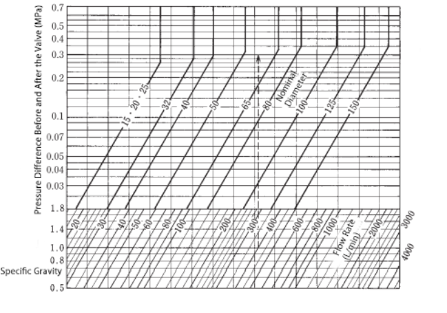
Nominal Diameter Selection
Select the appropriate nominal diameter using the nominal diameter selection chart. If the viscosity exceeds 20 mm²/s, consider the flow rate adjusted for viscosity correction as shown below when making your selection.
If the set pressure and outlet-side pressure are not constant within a certain range, select the nominal diameter based on the minimum differential pressure, which is determined by the set pressure and outlet-side pressure.
If the differential pressure is less than 0.1 MPa, add the offset value to the differential pressure when selecting the nominal diameter. Avoid selecting an excessively large back pressure valve, as this is more economical.
Disassembly and Maintenance Space Requirements
| Nominal Diameter | 15–32 | 40・50 | 65・80 | 100 | 125 | 150 |
|---|---|---|---|---|---|---|
| Upward Space from Pipe Center (mm) | 470 | 480 | 640 | 730 | 930 | 1220 |
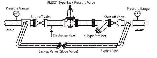
Piping Example
- It can be installed and used on both horizontal and vertical piping. However, for hot water, there is a risk of air blockage, so it cannot be used in a vertical pipe with an upward flow direction from the bottom.
- It is recommended to install a straight pipe section of at least 300 mm (for nominal diameters 15–25), 600 mm (for nominal diameters 32–40), 900 mm (for nominal diameters 50–100), and 1200 mm (for nominal diameters 125–150) before and after the back pressure valve as much as possible. This will ensure more stable operation.