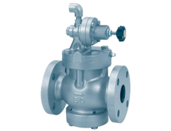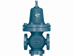
- Engineers designed the RMD31 type back pressure valve for low-pressure applications.
- The valve adopts an outlet pressure balance method, minimizing the impact of outlet side pressure fluctuations on the primary side pressure.
- The valve body incorporates synthetic rubber, ensuring excellent sealing performance when closed.
Specifications and Materials RMD31L
| Fluid | Primary Side Pressure Range (kPa) | Temperature (℃) | Main Component Materials | Pipe Connection | ||||
| Valve Body | Valve Element / Diaphragm | Diaphragm Retainer / Valve Seat & Liner | Valve Stem | Spring Cover | ||||
| Air and other non-corrosive gases | 10~50 | 0~80 | Cast Iron | Synthetic Rubber | Bronze / Stainless Steel | Stainless Steel | Cast Iron | Flange JIS 10K Full-Face |
| Cast Steel | ||||||||
| Stainless Steel Casting | Stainless Steel | |||||||
Note (1): The greater the difference between the set pressure and the outlet pressure, the larger the valve becomes.
Cv Value
| Nominal Diameter (mm) | 15・20・25 | 32 | 40 | 50 | 65 | 80 | 100 | 125 | 150 |
|---|---|---|---|---|---|---|---|---|---|
| Cv (Flow Coefficient) | 3.9 | 6.3 | 8.3 | 13 | 21 | 29 | 50 | 76 | 109 |
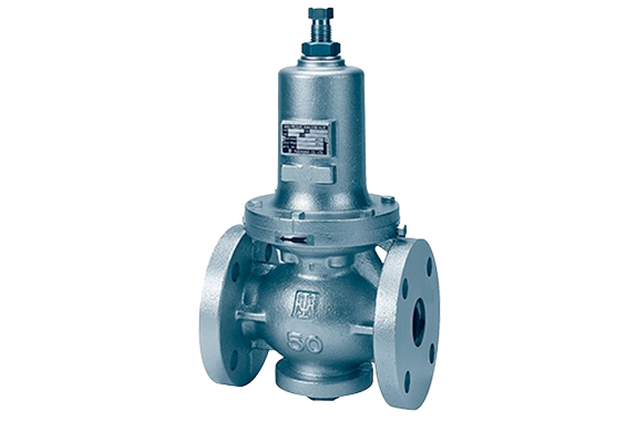
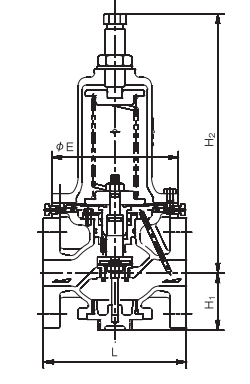
Structure and Dimensions RMD31L
Dimensions and Weight
| Nominal Diameter (mm) | Valve Body: Cast Iron | Valve Body: Cast Steel or Stainless Steel Casting | ||||||||
|---|---|---|---|---|---|---|---|---|---|---|
| L | H₁ | H₂ | E | Weight (kg) | L | H₁ | H₂ | E | Weight (kg) | |
| 15 | 196 | 70 | 363 | 155 | 12 | 206 | 70 | 363 | 155 | 16 |
| 20・25 | 200 | 70 | 363 | 155 | 13 | 210 | 70 | 363 | 155 | 17 |
| 32 | 175 | 70 | 363 | 155 | 14 | 220 | 70 | 363 | 155 | 18 |
| 40 | 190 | 80 | 371 | 155 | 16 | 220 | 80 | 371 | 155 | 21 |
| 50 | 195 | 80 | 371 | 155 | 17 | 225 | 80 | 371 | 155 | 22 |
| 65 | 230 | 104 | 484 | 210 | 34 | 280 | 104 | 484 | 210 | 38 |
| 80 | 250 | 104 | 484 | 210 | 35 | 280 | 109 | 484 | 210 | 39 |
| 100 | 290 | 127 | 530 | 250 | 58 | 330 | 127 | 530 | 250 | 65 |
| 125 | 365 | 174 | 685 | 320 | 98 | 380 | 174 | 685 | 320 | 114 |
| 150 | 415 | 207 | 897 | 380 | 150 | 470 | 207 | 897 | 380 | 162 |
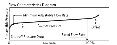
Nominal Diameter Selection RMD31L
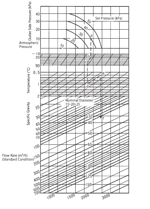
Please select the appropriate nominal diameter using the nominal diameter selection chart.
If the set pressure and outlet pressure fluctuate within a certain range, use the smallest pressure difference for selection.
Example of Use
- Set Pressure: 40 kPa
Outlet Pressure: 10 kPa
Temperature: 60°C
Specific Gravity: 0.6 (compared to air)
Flow Rate: 110 m³/h (Standard Condition)
Selection Process:
Pressure Adjustment:
Find the intersection of outlet pressure (10 kPa) and set pressure (40 kPa) → mark point a, then move downward.
Temperature Adjustment:
The reference temperature is 20°C (standard).
If the flow temperature is 20°C, continue straight down.
For 60°C, follow the 60°C correction line diagonally → find intersection b, then move downward.
Specific Gravity Adjustment:
The reference specific gravity is 1.0 (air).
If the fluid has a specific gravity of 1.0, continue straight down.
For 0.6, follow the 0.6 correction line diagonally → find intersection c, then move downward.
Flow Rate Adjustment:
From point c, move downward and find the intersection with 110 m³/h flow rate → mark point f.
Point f falls between nominal diameters 32 and 40.
Since choosing a larger size is recommended, nominal diameter 40 is the most suitable selection.
Disassembly and Maintenance Space Requirements
| Nominal Diameter (mm) | 15–32 | 40・50 | 65・80 | 100 | 125 | 150 |
|---|---|---|---|---|---|---|
| Upward Space from Pipe Center (mm) | 520 | 530 | 650 | 730 | 1010 | 1330 |
- Install the valve upright on a horizontal pipeline.
- If the fluid is air or similar and the outlet side is open to the atmosphere, the double-dashed line section is not required.