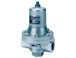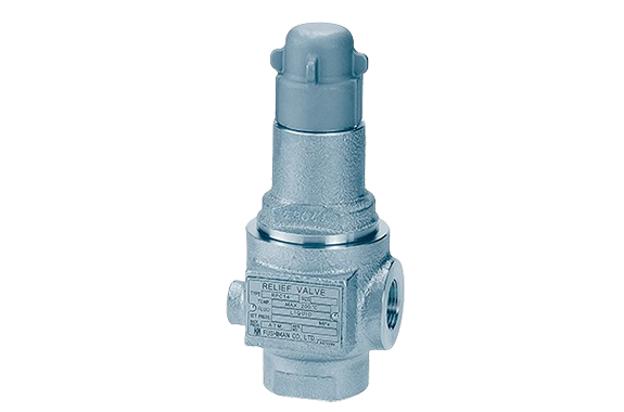
- This safety relief valve is made entirely of stainless steel, including the spring protection tube, providing excellent corrosion resistance and durability.
- Other characteristics are the same as ductile iron 16K.
Specifications and Materials
| Shape | Sealed Type without Lever | |
| Fluid | Water, Oil, Non-Corrosive Liquid | |
| Pressure | Set 0.04–1.6 MPa (Back Pressure: 1.0 MPa or Less) | |
| Operating Temperature | 0–200°C | |
| Maximum Usable Viscosity | 2000 mm²/s (At Operating Temperature) | |
| Materials | Valve Body | Cast Iron |
| Valve Seat | Stainless Steel | |
| Valve Disc | Stainless Steel | |
| Valve Stem | Stainless Steel | |
| Spring Protection Tube | Cast Iron | |
| Adjustment Spring | Spring Steel, Piano Wire | |
| Cover | Cast Iron | |
| Adjustment Screw | Brass | |
| Applications | Pump Bypass, Back Pressure Valve | |
| Applicable Standards | Pressure Vessel Structural Standards | |
Note (1): We will also consider cases where the viscosity exceeds 2000 mm²/s.
When there is pressure (back pressure) on the discharge side, the blow-off pressure will differ from the valve’s set pressure.
Additionally, if the back pressure changes, the blow-off pressure will also change.
When there is back pressure, the inlet-side pressure will be the set pressure plus the back pressure.
The maximum inlet-side pressure is 1.6 MPa.
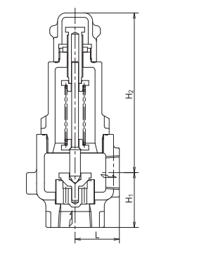
Dimensions and Mass
| Nominal Diameter (Inlet × Outlet) | Face-to-Face Distance | Height (H₂) | Pipe Connection | Mass (kg) | ||
|---|---|---|---|---|---|---|
| L | H₁ | Inlet | Outlet | |||
| 15 × 15 | 38 | 48 | 129 | JIS Rc Threaded | JIS Rc Threaded | 1.5 |
| 20 × 20 | 38 | 48 | 129 | JIS Rc Threaded | JIS Rc Threaded | 2 |
| 25 × 25 | 44 | 56 | 140 | JIS Rc Threaded | JIS Rc Threaded | 3 |
| 32 × 32 | 51 | 70 | 162 | JIS Rc Threaded | JIS Rc Threaded | 4 |
| 40 × 40 | 57 | 75 | 182 | JIS Rc Threaded | JIS Rc Threaded | 5 |
RPC14 Model Water Discharge Volume (Based on General Discharge Volume Calculation Formula)
| Nominal Diameter | 15 | 20 | 25 | 32 | 40 | 50 | 65 | 80 |
| Seat Bore Diameter D (mm) | 20 | 20 | 25 | 32 | 40 | 50 | 65 | 80 |
| Lift l (mm) | 0.28 | 0.5 | 0.63 | 0.8 | 1.0 | 1.25 | 1.63 | 2.0 |
| Set Pressure (MPa·G)/ Blowout Area A (mm²) | 12.4 | 22.2 | 34.9 | 56.8 | 88.8 | 138.8 | 235.3 | 355.3 |
| 0.1 | 423 | 758 | 1191 | 1939 | 3032 | 4740 | 8036 | 12134 |
| 0.2 | 598 | 1072 | 1685 | 2743 | 4289 | 6704 | 11364 | 17160 |
| 0.3 | 733 | 1313 | 2064 | 3360 | 5252 | 8210 | 13919 | 21017 |
| 0.4 | 847 | 1516 | 2383 | 3879 | 6065 | 9480 | 16072 | 24269 |
| 0.5 | 946 | 1695 | 2665 | 4337 | 6781 | 10600 | 17969 | 27133 |
| 0.6 | 1037 | 1857 | 2919 | 4751 | 7428 | 11611 | 19684 | 29723 |
| 0.7 | 1120 | 2006 | 3153 | 5132 | 8024 | 12542 | 21261 | 32105 |
| 0.8 | 1197 | 2144 | 3371 | 5486 | 8578 | 13408 | 22729 | 34321 |
| 0.9 | 1270 | 2274 | 3575 | 5819 | 9098 | 14221 | 24108 | 36403 |
| 1.0 | 1339 | 2397 | 3769 | 6134 | 9590 | 14990 | 25412 | 38373 |
| 1.1 | 1404 | 2514 | 3953 | 6433 | 10058 | 15722 | 26653 | 40246 |
| 1.2 | 1467 | 2626 | 4129 | 6720 | 10505 | 16421 | 27838 | 42035 |
| 1.3 | 1526 | 2733 | 4297 | 6994 | 10934 | 17092 | 28975 | 43752 |
| 1.4 | 1584 | 2836 | 4459 | 7258 | 11347 | 17737 | 30068 | 45403 |
| 1.5 | 1640 | 2936 | 4616 | 7513 | 11746 | 18359 | 31124 | 46997 |
| 1.6 | 1694 | 3032 | 4767 | 7759 | 12131 | 18961 | 32145 | 48538 |
| 1.7 | 1746 | 3126 | 4914 | 7998 | 12504 | 19545 | 33134 | 50032 |
| 1.8 | 1796 | 3216 | 5057 | 8230 | 12867 | 20112 | 34094 | 51482 |
| 1.9 | 1845 | 3304 | 5195 | 8455 | 13219 | 20663 | 35029 | 52893 |
| 2.0 | 1893 | 3390 | 5330 | 8675 | 13563 | 21200 | 35939 | 54267 |
- The discharge volume calculation formula is based on the calculation formula for relief valves in the High-Pressure Gas Safety Act.
- This table applies when the valve outlet pressure is atmospheric pressure and the overpressure is 25%.
- If G ≠ 1, multiply the values in the table by the corresponding G value to obtain the required discharge volume.
R101-1BHA Model Water Discharge Volume (Based on General Discharge Volume Calculation Formula)
| Nominal Diameter | 15-20 | 25 | 32 | 40 |
| Seat Bore Diameter D (mm) | 20 | 25 | 32 | 40 |
| Lift l (mm) | 0.7 | 0.8 | 1.0 | 1.3 |
| Set Pressure (MPa·G)/ Blowout Area A (mm²) | 43.9 | 62.8 | 100.5 | 163.3 |
| 0.1 | 1499 | 2144 | 3432 | 5645 |
| 0.2 | 2120 | 3033 | 4854 | 7983 |
| 0.3 | 2596 | 3714 | 5945 | 9778 |
| 0.4 | 2998 | 4289 | 6864 | 11291 |
| 0.5 | 3352 | 4795 | 7675 | 12623 |
| 0.6 | 3672 | 5253 | 8407 | 13828 |
| 0.7 | 3966 | 5674 | 9081 | 14936 |
| 0.8 | 4240 | 6066 | 9708 | 15967 |
| 0.9 | 4497 | 6434 | 10297 | 16936 |
| 1.0 | 4741 | 6782 | 10854 | 17852 |
| 1.1 | 4972 | 7113 | 11383 | 18724 |
| 1.2 | 5193 | 7429 | 11890 | 19556 |
| 1.3 | 5405 | 7733 | 12375 | 20355 |
| 1.4 | 5609 | 8025 | 12842 | 21123 |
| 1.5 | 5806 | 8306 | 13293 | 21865 |
| 1.6 | 5997 | 8579 | 13729 | 22582 |
- The discharge volume calculation formula is based on the calculation formula for relief valves in the High-Pressure Gas Safety Act.
- This table applies when the valve outlet pressure is atmospheric pressure and the overpressure is 25%.
- If G ≠ 1, multiply the values in the table by the corresponding G value to obtain the required discharge volume.