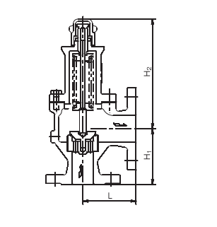
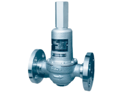
Fushiman RPC14 relief valve

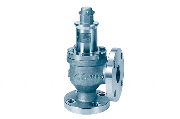
Manufacturer:  Fushiman Co.,LTD.
Model: RPC14

ModelNominal diameterfluidSet pressureMaximum operating temperatureBody MaterialConnection
RPC1415〜8.Liquid0.04 to 1.6 MPa200℃FCFflange

Features

RPC14 type ・ Cast iron ・ 16K ・ Same as the screw-in shape.
 High-pressure gas equipment certified products can also be manufactured.

  • If there is pressure (back pressure) on the outlet side, the blow-off pressure will differ from the valve’s set pressure.
    Additionally, if the back pressure changes, the blow-off pressure will also change.
    When there is back pressure, the inlet pressure will be the set pressure plus the back pressure. The maximum inlet pressure is the same as the nominal flange pressure.

Specifications and Materials

ShapeLeverless Sealed Type
FluidWater, Oil, Non-Corrosive Liquids
PressureSet Pressure: 0.04–2.0 MPa (Back Pressure: 1.0 MPa or less)
Operating Temperature一 5〜+200֯C一 3〇〜+200֯C
Maximum Usable Viscosity2000 mm²/s (At Operating Temperature) (※1)
MaterialValve BoxCast SteelStainless Steel Cast Steel
Valve SeatStainless SteelStainless Steel ・ Stellite Overlay
Valve BodyStainless SteelStainless Steel ・ Stellite Overlay
Valve StemStainless SteelStainless Steel
Spring Protection TubeMild Steel, Cast SteelStainless Steel
Adjustment SpringSpring Steel, Piano WireStainless Steel
LidStainless Copper, Mild SteelStainless Steel
Adjustment ScrewStainless SilkStainless Steel
ApplicationPump Bypass, Back Pressure ValvePump Bypass, Back Pressure Valve
Applicable StandardsPressure Vessel Structural StandardsPressure Vessel Structural Standards

Note (1): We will also consider cases where the viscosity exceeds 2000 mm²/s.

Remarks:

  1. For high-pressure gas equipment certified products, please specify.
  2. For valve boxes made of cast bronze with nominal diameters of 20, 25, and 40, we manufacture up to a set pressure of 3 MPa.

Dimensions and Mass

Nominal Diameter (Inlet × Outlet)Face-to-Face DimensionsHeight (H₂)Pipe ConnectionWeight
LHiInletOutlet
15X 208583143JIS 10K JIS 20K Flat-FacedJIS 10K Full-Faced4.1
20 x 2585851434.8
25 x 3290901587
32 x 4095951839.7
40 x 5010010520611.7
50 x 6511511525017.3
65 x 8013013031125
80XW014514536637.9
20 x 2586.583143ASME-JPI 150RFASME-JPI 150RF4.8
25 x 329189.51587
32 x 4097.5941839
40 x 50104.5105.520611.7
15X 208584.5143ASME-JPI 300RFASME-JPI 150RF4.1
20 x 2586.5861434.8
25 x 329192.51587
32 x 4097.597.51839.7
40 x 50104.510920611.7

RPC14 Model Water Discharge Volume (Based on General Discharge Volume Calculation Formula)

Nominal Diameter1520253240506580
Seat Bore Diameter D (mm)2020253240506580
Lift l (mm)0.280.50.630.81.01.251.632.0
Set Pressure (MPa·G)/ Blowout Area A (mm²)12.422.234.956.888.8138.8235.3355.3
0.14237581191193930324740803612134
0.2598107216852743428967041136417160
0.3733131320643360525282101391921017
0.4847151623833879606594801607224269
0.59461695266543376781106001796927133
0.610371857291947517428116111968429723
0.711202006315351328024125422126132105
0.811972144337154868578134082272934321
0.912702274357558199098142212410836403
1.013392397376961349590149902541238373
1.1140425143953643310058157222665340246
1.2146726264129672010505164212783842035
1.3152627334297699410934170922897543752
1.4158428364459725811347177373006845403
1.5164029364616751311746183593112446997
1.6169430324767775912131189613214548538
1.7174631264914799812504195453313450032
1.8179632165057823012867201123409451482
1.9184533045195845513219206633502952893
2.0189333905330867513563212003593954267
  1. The discharge volume calculation formula is based on the calculation formula for relief valves in the High-Pressure Gas Safety Act.
  2. This table applies when the valve outlet pressure is atmospheric pressure and the overpressure is 25%.
  3. If G ≠ 1, multiply the values in the table by the corresponding G value to obtain the required discharge volume.

R101-1BHA Model Water Discharge Volume (Based on General Discharge Volume Calculation Formula)

Nominal Diameter15-20253240
Seat Bore Diameter D (mm)20253240
Lift l (mm)0.70.81.01.3
Set Pressure (MPa·G)/ Blowout Area A (mm²)43.962.8100.5163.3
0.11499214434325645
0.22120303348547983
0.32596371459459778
0.429984289686411291
0.533524795767512623
0.636725253840713828
0.739665674908114936
0.842406066970815967
0.9449764341029716936
1.0474167821085417852
1.1497271131138318724
1.2519374291189019556
1.3540577331237520355
1.4560980251284221123
1.5580683061329321865
1.6599785791372922582
  1. The discharge volume calculation formula is based on the calculation formula for relief valves in the High-Pressure Gas Safety Act.
  2. This table applies when the valve outlet pressure is atmospheric pressure and the overpressure is 25%.
  3. If G ≠ 1, multiply the values in the table by the corresponding G value to obtain the required discharge volume.

REQUEST QUOTATION

PAYMENT

payment-methods

Return Top