Fushiman Co.
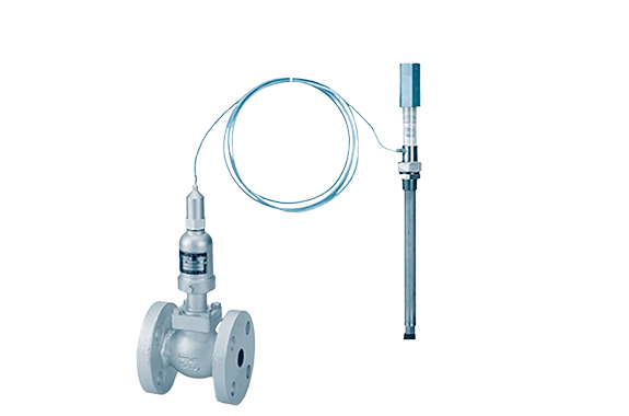
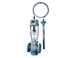
Fushiman TL10H type temperature control valve
Manufacturer: Fushiman Co.,LTD.
Model: TL10H
| Model | Nominal diameter | Pressure | Temperature setting | Body Material | Connection |
|---|---|---|---|---|---|
| TL10H | 15–50 | Max. 1.0MPa | 10 to 110°C | FCD | Flange (screw-in temperature sensor) |
Features
Compared to conventional bellows-type (single-seat valves), it offers a larger capacity with less seat leakage, and is also compact and lightweight.
The actuator can be easily attached and detached from the valve body, allowing wide-range temperature adjustment with a single actuator and capillary tube.
Designed to be less affected by fluid pressure.
The capillary tube uses a liquid expansion system, so the installation angle is flexible.
The fluid inside the capillary tube and actuator uses water or alcohol-based liquid, so no special disposal by a waste treatment contractor is required.
Main Specifications
| Application & Model Name | For heating use: TL10H Type | |||||
| Temperature Setting Range | 10 to 110°C | Refer to standard temperature setting range | ||||
| Nominal Diameter | 15 | 20 | 25 | 32 | 40 | 50 |
| Valve Type | Single-seat (straight plug) | |||||
| Seat Leakage | Less than 0.05% of rated flow | |||||
| Maximum Operating Pressure of Valve Body (MPa) | 1.0 | 0.7 | ||||
| Valve Body Pipe Connection | Flange JIS 10K full-face | |||||
| Valve Flow Medium | Steam (185°C or lower), hot water | |||||
| Applicable Pressure for Capillary Tube (MPa) | 1.0 MPa or less (external pressure) | |||||
| Capillary Tube Connection Standard | JIS pipe taper thread | |||||
| Capillary Tube Length | Standard length 3 m (up to max. 8 m) | |||||
Note: The ambient temperature around the valve should be (set valve temperature – 10°C) or lower.
Standard Temperature Setting Range
| Type | Temperature Setting Range | Heat Resistance |
|---|---|---|
| Low Temp | 10°C or higher, 70°C or lower | Setting temp +10°C |
| Standard | 50°C or higher, 110°C or lower | Setting temp +15°C* |
* The maximum temperature is 120°C.
Valve Opening/Closing Temperature Difference
| Category | Standard / Low Temp Use |
|---|---|
| CT 3m | 5°C or less |
Materials of Main Components
| Part Name | Material |
|---|---|
| Valve Body | Spheroidal Graphite Cast Iron |
| Upper Cover | Spheroidal Graphite Cast Iron |
| Valve Plug | Stainless Steel |
| Valve Seat | Stainless Steel |
| Spring Cover | Cast Iron |
| Piston Chamber | Brass |
| Capillary Tube (CT) | Copper Tube(2) |
| Capillary Bulb | Stainless Steel Tube |
Dimensions, Weight, and Cv Value
| Category | Nominal Diameter (mm) | |||||
|---|---|---|---|---|---|---|
| 15 | 20 | 25 | 32 | 40 | 50 | |
| L (mm) | 120 | 120 | 130 | 150 | 160 | 180 |
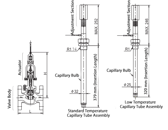
| H (mm) | 236 | 236 | 236 | 244 | 244 | 249 |
| Weight (kg) | 7 | 7.5 | 8.5 | 11 | 12 | 14 |
| Cv Value | 3.5 | 3.5 | 5 | 8 | 10 | 16 |
Structure and Dimensions
Nominal Diameter Selection (Example)
If you are using superheated steam, please contact us.
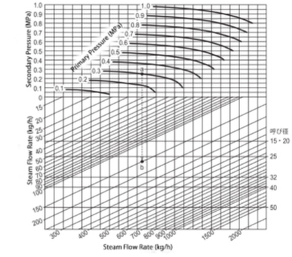
Example of using the selection chart
Specifications: Fluid – Saturated steam
Primary side pressure: 0.3 MPa
Flow rate: 150 kg/h
① Assume the allowable valve pressure drop ΔP is 0.05 MPa. Determine the intersection point between the secondary side pressure 0.25 MPa (0.3 – 0.05 MPa) and the primary side pressure 0.3 MPa.
② From intersection point A, draw a vertical line downward and find point B where it intersects with the flow rate of 150 kg/h.
③ Point B falls between nominal diameters 25 and 32, so select the larger one, which is 32.
Notes:
Plan so that the flow velocity at the primary pressure side is 30 m/s or lower.
The allowable valve pressure drop ΔP (pressure difference across the valve) should be 0.2 MPa or less.
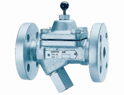
Related Products
REQUEST QUOTATION

PAYMENT

LINK


