Gore (日本ゴア)
GORE Microwave/RF Assemblies for Civil Aircraft
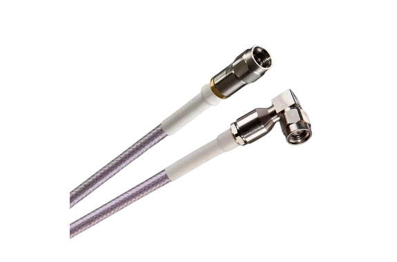
Manufacturer: Gore (日本ゴア)
Made in Japan
Model: Microwave/RF Assemblies
Overview of Microwave/RF Assemblies
According to our independent studies and research, globally more than 75% of microwave/RF assemblies are frequently replaced because of damage during installation or operation. That’s a high percentage of assembly failure that involves taking the aircraft out of service, extra labor to replace assemblies, and more money that can add up fast! With more passengers traveling these days for business or leisure, the industry needs avionics to operate reliably and aircraft to remain in service longer.
Proven Performance & Reliability
GORE Microwave/RF Assemblies ensure optimal electrical and mechanical performance consistently for the duration of the aircraft. They deliver dependable signal integrity for superior radio frequency up to 32 gigahertz (GHz) in Ka/Ku-Band applications.
Our assemblies are also proven to provide outstanding shielding effectiveness with excellent insertion/return loss for less RF interference among multiple satellite communications systems. Since the connector choice determines a specific assembly’s shielding effectiveness, we offer an assortment of connectors designed specifically to complement assembly performance, minimizing loss and reflection for optimized signal transmission.
But that’s not all. We combine durability in a small, low-weight construction so that mechanical strength isn’t compromised. Our assemblies ensure high-quality signals in harsh environments, like complex routing, maintenance activities, and flight conditions. Their smaller size also means more flexibility, so aircraft maintainers will find them easy to route — particularly for conduit installation or in areas that require little to no maintenance activity.
GORE Microwave/RF Assemblies are proven to maintain high-quality signals with proven shielding effectiveness for longer service life, less downtime, and fewer total costs.
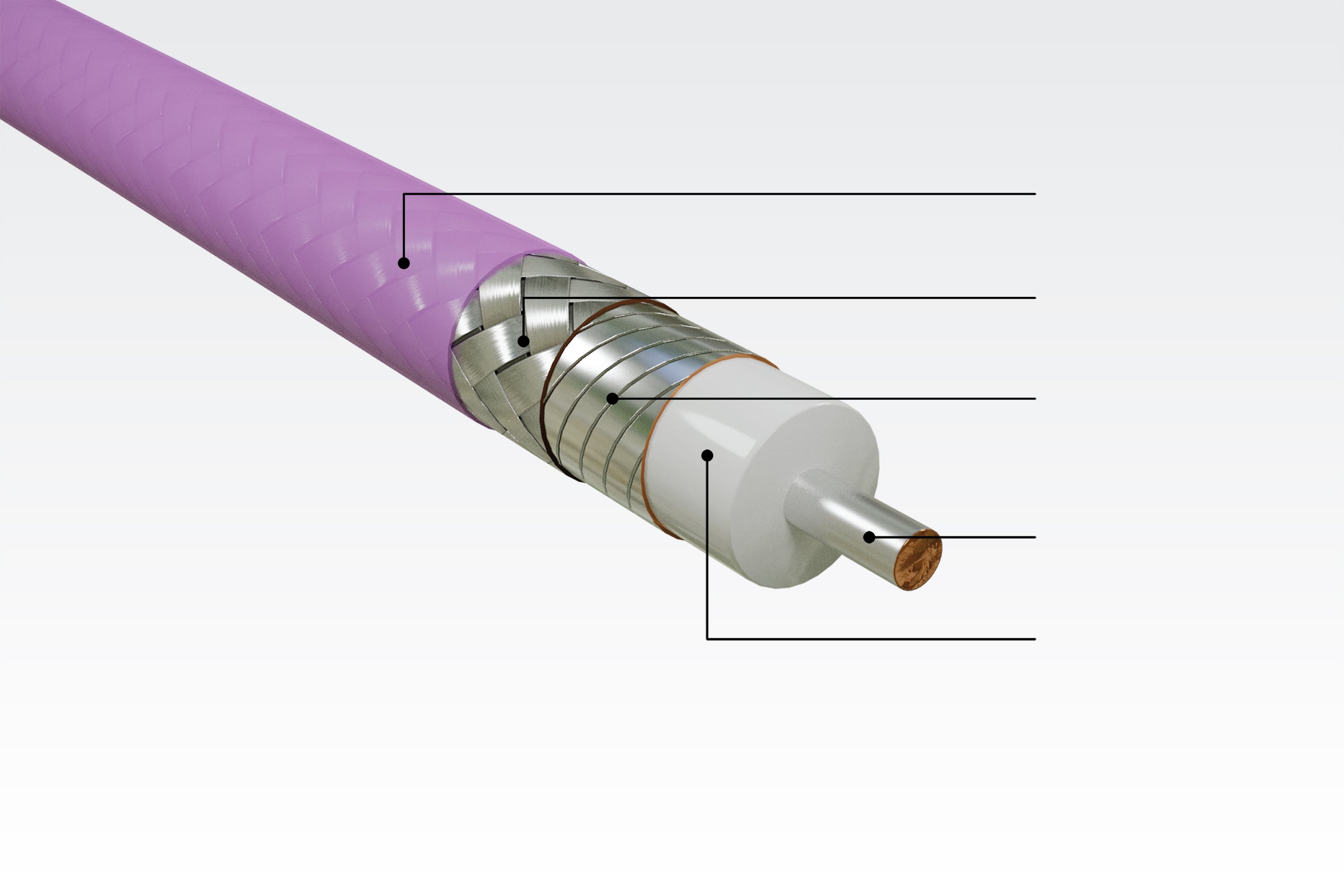
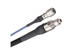
Durable, compact construction of GORE Microwave/RF Assemblies
Applications
GORE Microwave/RF Assemblies are engineered to perform reliably in commercial airborne applications, including:
- Ka-Band SATCOM antennas
- Ku-Band SATCOM antennas
Benefits
GORE Microwave/RF Assemblies provide system architects and engineers with many benefits that improve electrical and mechanical performance such as:
- dependable signal integrity for superior radio frequency up to 32 GHz
- outstanding shielding effectiveness with excellent insertion/return loss
- greater mechanical strength that tolerates harsh aerospace environments
- easy installation due to smaller diameters with greater flexibility and tight bend radius
- low-weight assembly for improved fuel efficiency and increased cargo
- longer system life for less downtime and lower total costs
- robust, low-profile connector options for increased design flexibility
- proven performance with approved aerospace materials through qualification testing
Properties
These values demonstrate the electrical, mechanical and environmental performance of GORE Microwave/RF Assemblies.
| Electrical Propertya | Cable Type | ||
|---|---|---|---|
| 5H | G5 | 8W | |
| Maximum Frequency (GHz) | 32 | 18 | 18 |
| Optimized Frequency (GHz) | 17.5 – 22.0 27.0 – 32.0 | DC-18 | DC-18 |
| Guaranteed VSWR (dB through Max Frequency) Straight-to-Straight Connector Straight-to-Right Angle Connector | 1.35:1 1.4:1 | 1.35:1 1.4:1 | 1.35:1 1.4:1 |
| Typical Insertion Loss (dB/m [dB/ft]) | 1.53 (0.47) | 1.13 (0.34) | 0.75 (0.23) |
| Attenuation at Max Frequency (dB/m [dB/ft]) | 1.58 (0.48) | 1.06 (0.32) | 0.63 (0.19) |
| Typical Phase Stability (Degree) | +/- 5.0 | +/- 2.0 | +/- 15.0 |
| Typical Amplitude Stability (dB) | 0.05 | < +/- 0.05 | < +/- 0.05 |
| Standard Impendence (Ohms) | 50 ± 1 | ||
| Velocity of Propagation (Nominal) (%) | 85 | ||
| Time Delay (Nominal) (ns/m [ns/in]) | 3.94 (0.10) | ||
| Capacitance (pF/m [pF/ft]) | 72.7 (22.1) | 80.3 (24.4) | 78.6 (24.0) |
| Shielding Effectiveness (dB through Max Frequency) | 101 | > 100 | > 100 |
| Dielectric Constant (Nominal) | 1.4 | ||
| Dielectric Withstanding Voltage (Vrms) Conductor-to-Conductor Conductor-to-Shield | 500 | 1000 | 1500 |
a Specifications for Type 5H are based on a 0.6 m (23.6 in) assembly length, Types G5 and 8W are based on a 0.9 m (36 in) assembly length, and the maximum frequency with straight connectors.
| Mechanical / Environmental Property | Cable Type | ||
|---|---|---|---|
| 5H | G5 | 8W | |
| Jacket Material | PFA | ||
| Jacket Color | Purple | ||
| Center Connector | Solid, Silver-Plated Copper | ||
| Dielectric Material | ePTFE | ||
| Nominal Outer Diameter (mm [in]) | 4.3 (0.17) | 4.8 (0.19) | 8.1 (0.32) |
| Nominal Weight (g/m [lbs/1000 ft]) | 42.0 (28.2) | 52.5 (35.3) | 144.4 (97.0) |
| Minimum Bend Radius (mm [in]) | 25.4 (1.0) | 25.4 (1.0) | 50.8 (2.0) |
| Temperature Range (°C) | -95 to +155 | -55 to +125 | -55 to +125 |

