- Home
- Products
- Hakaru XM2-110-9 High-Performance (Single-Phase Two-Wire, Single-Phase Three-Wire, Three-Phase Three-Wire)
Hakaru
Hakaru XM2-110-9 High-Performance (Single-Phase Two-Wire, Single-Phase Three-Wire, Three-Phase Three-Wire)
Manufacturer: HAKARU PLUS CORPORATION
Model: XM2-110-9
Product Description
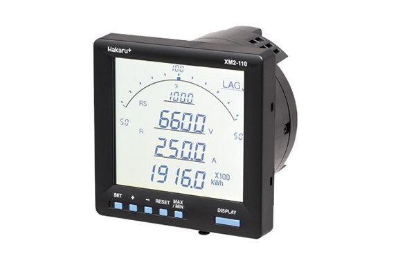
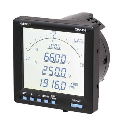
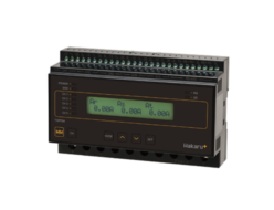
The high-performance electronic multimeter XM2-110 is a digital instrument that combines an indicating instrument and a converter.
Up to four measurement elements can be displayed at once: one bar graph and three digital displays.
The size is a 110mm square cylindrical body with a depth of 89mm, making it thin and compact.
The LCD panel uses the STN method, achieving higher contrast and a wider viewing angle than conventional products.
Features
Four measurement items, including a bar graph (with digital display) and three digital displays, can be displayed simultaneously on the LCD panel.
Measurement items that were previously measured using multiple mechanical instruments can now be consolidated into one unit.
Display items can be set as desired.
Display items: Current, Voltage (Line voltage, Phase voltage), Power, Reactive power, Power factor, Energy, Reactive energy, Frequency, Demand current, Maximum demand current, Demand power, Maximum demand power, Extended current measurement, Harmonic current, Harmonic voltage, Zero-phase voltage, Maximum zero-phase voltage, Io, Ior
With a wide viewing angle of 75° up and down and 70° left and right, it can be installed anywhere.
The internal structure has been redesigned to make it thinner and more compact, with a depth of just 89mm. In addition to the conventional button operation settings, by utilizing the dedicated PC setting software, various parameters can be instantly set without operating the keys on the main unit, even when setting up multiple meters. In addition, the settings can be saved and read, making maintenance easier.
The LCD panel allows you to set the backlight automatic shut-off time and adjust the brightness.
The output test function allows for a simulated output signal to be sent externally, even without input, as long as there is a power supply.
- Analog output: Zero/span output operation possible
- Pulse output: Output operation possible for each pulse
- Alarm output: Alarm output ON/OFF switching operation possible
- Communication output: Transmission data output operation possible
The phase detection function makes it easy to check the voltage phase sequence and CT direction, making it ideal for sites where mechanical instruments are used.
You can choose from four backlight colors to suit your site: amber (standard), white, orange, and green.
Measurements can be made for single-phase two-wire, single-phase three-wire, and three-phase three-wire (selectable settings).
It can measure harmonics (current and voltage) up to the 15th order and convert it into 5th order measurements.
Depending on the model, the following optional functions can be installed: Simultaneous installation of
- 4 analog outputs, pulse output, and alarm output
- RS-485 + contact status input x 3 points, pulse output, and alarm output
- RS-485 communication (Modbus/RTU) + contact status input x 3 points, pulse output, and alarm output
- CC-Link communication + contact status input x 3 points, pulse output, and alarm output
- 6 analog outputs, pulse output, and alarm output
specification
Specification
| item | specification |
|---|---|
| phase wire system | ・Single-phase 2-wire , single-phase 3-wire , and three-phase 3-wire (setting switchable) |
| Voltage Input | ・AC110V ・AC220V (setting switch) |
| Current Input | ・5A ・1A (model designation) |
| Auxiliary power supply | ・AC85~264V or DC85~143V ・DC20~40V ・DC30~60V (specify model) |
| External Operation Input | 2 points |
Digital display
| Measurement item (number of digits) | Input Rating | inherent error | remarks |
|---|---|---|---|
| Current (3・4) | 0~1A・0~5A | ±0.5% | Display unit A/kA switching |
| Line voltage (3, 4) | 0~150V・0~300V | ±0.5% | Display unit V/kV switching |
| Phase voltage (3, 4) | 0~150√3V・0~300√3V | ±0.5% | Display unit V/kV switching |
| Electricity (4) | 0~1kW・-1~0~1kW・0~2kW・-2~0~2kW | ±0.5% | Display unit switchable between W, kW and MW, negative display |
| Reactive Power (4) | 0~Lag1kvar・Lead1~0~Lag1kvar・0~Lag2kvar・Lead2~0~Lag2kvar | ±0.5% | Display units: var, kvar, Mvar switchable, with Lag and Lead display |
| Power factor (3) | Lead50~100~Lag50・Lead0~100~Lag0(%) | ±2.0% | Lag/Lead display, 1 decimal place |
| Electricity (6) | Digital display: multiplication factor x 1, x 10, x 100, x 1000 | ±2.0% ±2.5% | 5 to 120% of rated current (power factor = 1)10 to 120% of rated current (power factor = 0.5) |
| Reactive energy (6) | Digital display: multiplication factor x 1, x 10, x 100, x 1000 | ±2.5% ±2.5% ±3.0% | 10 to 120% of rated current (power factor = 0)20 to 120% of rated current (power factor = 0.866) 10% of rated current |
| Frequency (3) | 45~65Hz・45~55Hz・55~65Hz・ | ±0.5% | 1 decimal place |
| Demand current Maximum demand current (3/4) | 0~5A | ±0.5% | Demand time selection setting, heat conduction root calculation method |
| Demand power Maximum demand power (4) | 0-1kW, 0-2kW | ±0.5% | Demand time selection setting, heat conduction root calculation method |
| Current extension measurement (3, 4) | 0~5A・0~25A | ±8.0% | Display unit A/kA switching extended by 5 times (R phase only) |
| Harmonic current (3・4) | Total RMS value: 0~1A, 0~5ATotal distortion factor: 0~100% | ±2.5% | Display unit A/kA switching, R phase, S phase only measurement, total RMS value, total distortion factor, each order RMS value, each order distortion factor, fifth order converted RMS value, fifth order converted distortion factor, distortion factor up to 50% |
| Harmonic voltage (3, 4) | Total RMS value: 0 to 150V, 0 to 300VTotal distortion: 0 to 100% | ±2.5% | Display unit V/kV switch, RS phase, ST phase only measurement, total effective value, total distortion factor, each order effective value, each order distortion factor, fifth order converted effective value, fifth order converted distortion factor, distortion factor up to 50% |
| Zero-phase voltage (3, 4) Maximum zero-phase voltage (3, 4) | EVT: AC110V/AC190.5VZPD: AC7V/AC7.6V | ±1.0% | |
| Io (4) | AC0.8A | ±1.0% | Display unit A |
| Ior (4) | AC0.1A | ±10.0% | Display unit A |
Communication specifications
| method | item | Rating |
|---|---|---|
| RS-485 communication | Interface | RS-485 |
| 〃 | Transmission distance | Less than 1km (maximum 32 cars) |
| 〃 | communication speed | 1200・2400・4800・9600・19200bps |
| 〃 | Transmission cable | Shielded twisted pair wire (CPEV-S0.9φ) |
| 〃 | Termination resistor | Built-in 100Ω (terminal short-circuited to turn on termination resistor) |
| 〃 | Synchronization method | Start-stop synchronization method |
| 〃 | Communication Control Method | Polling selection method (half-duplex) |
| 〃 | Code used | ASCII |
| 〃 | Data format: Starbit | 1 bit |
| 〃 | Data method: Data | 7-bit |
| 〃 | Data format: Parity bit | even number |
| 〃 | Data format: Stop bit | 1 bit |
| RS-485 communication (Modbus) | Interface | RS-485 communication (Modbus) |
| 〃 | Transmission distance | Less than 1km (maximum 32 cars) |
| 〃 | communication speed | 1200・2400・4800・9600・19200bps |
| 〃 | Transmission cable | Shielded twisted pair wire (recommended: CPEV-S0.9φ) |
| 〃 | Termination resistor | Built-in 100Ω (terminal short-circuited to turn on termination resistor) |
| 〃 | Synchronization method | Start-stop synchronization method |
| 〃 | Communication Control Method | Polling selection method (half-duplex) |
| 〃 | Code used | RTU |
| 〃 | Data format: Starbit | 1 bit |
| 〃 | Data method: Data | 8-bit |
| 〃 | Data format: Parity bit | None or even number or odd number |
| 〃 | Data format: Stop bit | 1 or 2 bits |
| CC-Link communication | communication protocol | CC-Link Ver1.1/Ver2 (8x mode) |
| 〃 | communication speed | 156k・625k・2.5M・5M・10Mbps |
| 〃 | Number of occupied stations | Occupies one remote device station |
| 〃 | Configurable area codes | 1~64 |
| 〃 | Number of connectable devices | 42 units (when configured with this unit only) |
| 〃 | Word area (CC-Link Ver1.1) | Send and receive 4 words each (for analog data) |
| 〃 | Word area (CC-Link Ver2) | Send and receive 32 words each (for analog data) |
| 〃 | Bit area (CC-Link Ver1.1) | 32 bits for transmission and reception (for contact data) |
| 〃 | Bit area (CC-Link Ver. 2) | 256 bits for transmission and reception (for contact data) |
| Contact status input | Same as auxiliary power supply (operates when energized for 0.3 seconds or more, continuous energization possible) Maximum input current is 6mA or less. |
Related Products
-
Hakaru XM2-110-X108 Electronic Multimeter, 5-Point Contact Input Type
-
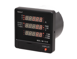
Hakaru RM-110 LED Type Digital Multimeter Standard Type
-
Hakaru TRP-M1MB Thin Subtractor
-
Hakaru TM2 Multi-Transducer
-
Hakaru CSA-132/136 Standard Box With Built-In LoRa Radio (Weather-Resistant Resin/Rod Antenna)
-
Hakaru TWP5M Power Converter 5-Circuit Power Multi-Measurement Type
REQUEST QUOTATION

PAYMENT

LINK


