IHARA SCIENCE CORPORATION
IHARA PSD-S Pre-Setting Device
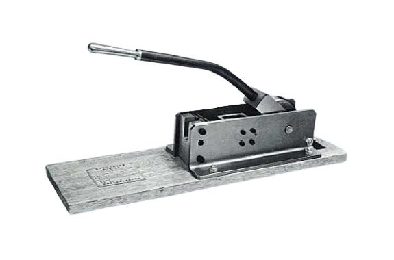
Product Made in Japan
Manufacturer: IHARA SCIENCE CORPORATION
Model: PSD-S
1. Structure and Function of Pre-Setting Device
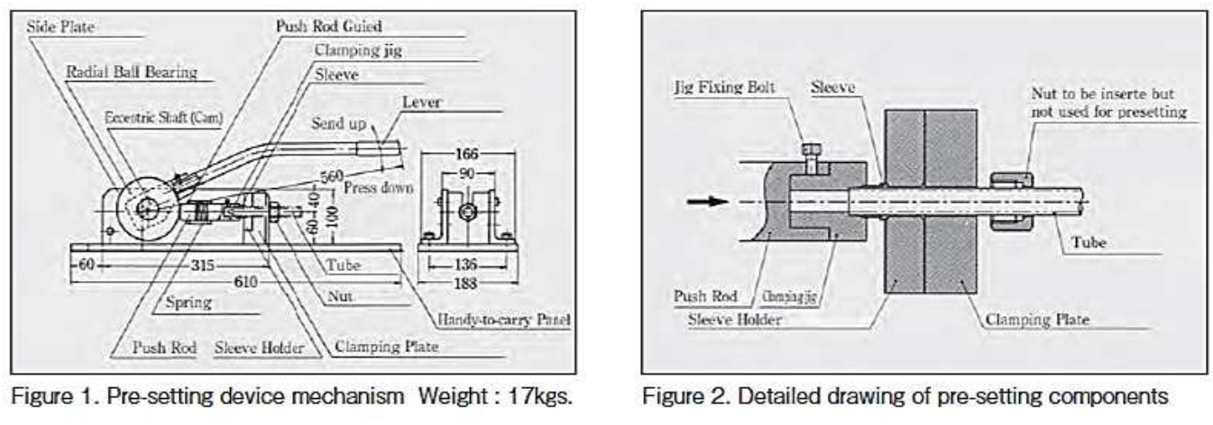
PSD-S This device performs pre-setting by cam mechanism as illustrated in the figure below for bite type fittings within the tube range of 4 to 20 mm outside diameter or 1/8B to 3/8B. By pressing the lever down, the clamping jig attached to the push rod slides toward the clamping plate by cam action and force the sleeve to bite into the tube.
2. STANDARD COMPONENTS
For pre-setting with this device (PSD-S) it will be necessary to select clamping jig and sleeve holder applicable to the outside diameter of the tube to be used. The clamping jigs and sleeve holders are not included with the pre-setting device and must be separately ordered.
| Tube OD | Clamping jig | Sleeve holder |
|---|---|---|
| 4 | PJS04-000N (PSD —SJ—4) | PJU04-00SN (PSD—SU—4) |
| 6 | PJS06-000E (PSD—SJ—6) | PJU06-00SE (PSD-SU-6E) |
| 8 | PJS08—000E (PSD—SJ—8) | PJU08-00SE (PSD-SU-8E) |
| 10 | PJS10- 000E (PSD—SJ —10) | PJU10-00SE (PSD-SU-10E) |
| 12 | PJS12- 000E (PSD—SJ—12) | PJU12-00SE (PSD-SU-12E) |
| 15 | PJS15—000E (PSD—SJ —15) | PJU15-00SE (PSD-SU-15E) |
| 16 | PJS16—000E (PSD—SJ—16) | PJU16-00SE (PSD-SU-16E) |
| 18 | PJS18-000E (PSD—SJ—18) | PJU18-00SE (PSD-SU-18E) |
| 20 | PJS20—000E (PSD—SJ—20) | PJU20-00SE (PSD-SU-20E) |
| 1/8B | PJSII—000N (PSD-SJ-G1/8) | PJU11-00SN (PSD-SU-G1/8) |
| 1/4B | PJS13-000E (PSD-SJ-G1/4) | PJU13-OOSN (PSD—SU—G1/4) |
| 3/8B | PJS17-000N (PSD-SJ-G3/8) | PJU17-00SN (PSD-SU-G1/8) |
3 CAUTION
1) Cut the tube at a right angle and remove all burrs from the outside and inside of the cut tube end.
CAUTION: Cut the tube aiming at an angle of 90° ±1° outer surface of the tube must be free from the scratched damage of more deeper than 0.1mm.
2) In case of bent tube, the straight portion of the tube must be longer than 80mm from both tube ends.
3) Lubricate the moving parts of the device with oil timely. CAUTION: Do not modify the device and jigs. The device may not function properly when modification has been performed.
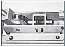 | 1. Raise the lever and open space between the push rod and the clamping plate.
|
 | 2. Attach a clamping jig of the same size as the tube.
|
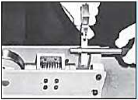 | 3. Insert the nut and the sleeve into the tube with correct order and direction, and set the sleeve holder between the nut and the sleeve. WARNING: Make sure the correct direction of sleeve. If the sleeve is facing the incorrect direction, the sleeve will not bite into the tube and tube slippage failure will result.
|
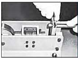 | 4. Mount the tube with the nut and the sleeve on the pre-setting device.
|
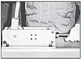 | 5. The tube end must be contacting and seated firmly against the shoulder of the clamping jig. WARNING: When clamping is performed with the tube end not contacting the shoulder of the pre-setting device, biting into the tube will not be satisfactory and cause the tube to slip.
|
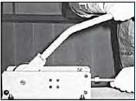 | 6. Push down on the lever.
|
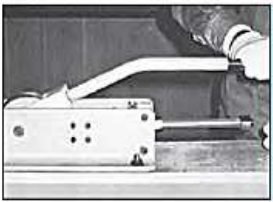 | 7. Clamp down on the lever until it can no longer be pressed. CAUTION: Press down on the lever until firmly contacting.
|
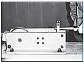 | 8. Lift up the lever to loose the clamp and remove the tube with the two-piece sleeve holder. The presetting operation completed. |
5. FINAL TIGHTENING
The tube that have been pre-set is now ready to be installed to the fitting body at the piping site. In the installing operation, the tightening torque while tightening the nut with a spanner will suddenly increase upon reaching a certain point called (sharp torque rise point), then from this point turn additionally 1/4 turn to complete the installation. WARNING: Perform tightening of the nut on firm footing, and ascertain the safety of the surrounding. CAUTION: Insufficient tightening can result in leakage and tube slippage. CAUTION: Clean the sleeve after pre-setting and the taper bore of the fitting body with cloth and blow clean with compressed air before assembling. When foreign material becomes caught, sealing function can be impaired.

